Showing posts with label Lectures. Show all posts

Saturday, December 12, 2020

Density of Aggregate - Bulk and Relative Density


Density is an important parameter for aggregate. For aggregates, density is determined by multiplying the relative density (specific gravity) of the aggregate times the density of water.

Bulk Density of Aggregate [1]

The bulk density or unit weight of an aggregate is the mass or weight of the aggregate that required to fill a container of a specified unit volume.

Bulk Density = Mass/volume

Key Features:

  • If the volume is unit then, Bulk Density= Mass.
  • Unit in kg/m3 or lb./ft3.
  • In this definition, the volume is that contains both the aggregates and the voids between aggregates particles. 
  • The approximate bulk density of aggregate that is commonly used in normal-weight concrete is between 1200-1750 kg/m3 (75-110 lb./ft3)
  • Here, the Standard test method for determining the bulk density of aggregates is given in ASTM C 29 (AASHTO T 19). [2]

Relative Density of Aggregate [1]

The relative density (specific gravity) of an aggregate is the ratio of its mass to the mass of an equal volume of water.

Relative Density = Mass of the Aggregate/Mass of equal volume of water

Key Features:

  • Most aggregates have a relative density between 2.4-2.9 with a corresponding particle (mass) density of 2400-2900 kg/m3 (150-181 lb./ft3).
  • Here, for coarse aggregates, the standard test method has been explained in ASTM C 127(AASHTO) and for fine aggregates, the standard test method has been explained in ASTM C 128 (AASHTO). [3] 
  • The relative density of an aggregate can be determined on an oven-dry basis or a saturated surface-dry (SSD) basis.

Thursday, December 10, 2020

PMP Course lectures


PMI defines the project management body of knowledge (PMBOK) as a term that describes the knowledge within the profession of project management. The project management body of knowledge includes proven traditional practices that are widely applied as well as innovative practices that are emerging in the profession.

Saturday, October 31, 2020

Quantity of Cement, Sand & Water required for Plastering:


Plastering refers to protecting a wall or ceiling by laying a plaster (Cement plaster). Plastering is done to remove surface imperfections caused by brickwork and to keep the surface smooth for painting.


There are many different types of plastering materials out of them, cement plaster is extensively used. Some other types of plastering materials include lime plaster, clay plaster, etc.


How to select the right plastering material for your house?

In any type of plastering two major factors are considered they are Surface Protection and the cost of material. If the quality of plastering is increased and taken higher, then the cost is affected. If price is considered and Quality of plaster are taken lesser importance then the surface protection is compromised.


Plastering material should be cheap and economical.

It should be durable enough to sustain any climatic changes in the entire life span of structure.

Plastering material should have excellent workability which can be applied during any weather conditions.

Let us calculate the quantity raw materials (Cement, Sand & water) required for cement plaster. Though the same process is applicable for any other types of plastering materials.


Contents [show]


Calculating the quantities of Cement & Sand required for plastering:

General points to be remembered in Plastering work calculation


The ratios mentioned in plastering are volumetric ratios of Cement & Sand (Ex. Cement: Sand = 1:5, 1 part of cement and 5 parts of sand in a mortar).

The overall thickness of plastering should be minimum 20mm including two coats.

Cement has a dry density volume of 1440Kg/m3

Each bag of cement weighs = 50 Kgs or 110 lbs.

The Volume of each cement bag = 50Kgs/1440 = 0.0348 m3.

The dry density of sand = 1600Kgs/m3

The plastering is done in two layers (two coats): The first coat of plastering is laid with the thickness of minimum 12mm (usually ranges between 12-15mm) and this coat is called as a Rough coat or Primary coat.

The second coat should be laid with the thickness of 8mm and this is called as a Finish coat or Secondary coat of plastering.

Total Plastering = First coat + Second Coat


Different ratios of Cement mortar used for plastering are tabulated below:

Mix Ratio             Areas of usage

1:6 & 1:5              This ratio is usually used for Internal plastering of bricks

1:4          Used for Ceiling and external walls

1:3          As it’s a rich mortar mix and it is used where external walls are prone to severe climatic conditions.

It is also used for repair works.


Steps involved in calculation of plastering quantities:

Find the total area of wall to be plastered in Sqm (m2).

Consider the ratio and thickness of plastering

Calculate the Total Volume of Plastering

Find out the Volume of Cement and Sand individually for both the coats

Calculate the total volume of cement & Sand required for plastering

Now coming to the calculation part,


We are considering the below values for calculation purpose:


Wall width and height is 10m and 10m.

Ratio of First coat of plastering (Cement: Sand = 1:5) with the thickness of 12mm.

the ratio of secondary coat of plastering (Cement: Sand = 1:3) with the thickness of 8mm.

Step 1: Calculate the Area of Plastering

Area = width x height = 10 x 10 = 100m2


Step 2: Find the Volume of Plastering


Volume of First Coat = Area of Plastering x Thickness of Plastering


= 100m2 x 12mm (Convert mm to m)


= 100×0.012 = 1.2m3


Hence, Volume of First Coat of Plastering = 1.2m3


The volume of Second Coat = Area of Plastering x Thickness of Plastering


= 100m2 x 8mm (Convert mm to m)


= 100×0.008 = 0.8m3


Therefore, Volume of Second coat of plastering = 0.8m3

 a

Step 3: Finding the individual quantities of Cement and Sand.

First coat ratio = 1:5 (1 part of Cement and 5 parts of Sand)


Total parts = 1+5 = 6


Quantity of Cement required for First coat =


(Total Volume of first coat plastering x No. of Parts of cement) ÷ Total Parts


= 1.2 x 1/6 = 0.2m3


Quantity of Sand required for First coat =


(Total Volume of first coat plastering x No. of parts of sand) ÷ Total Parts


= 0.8 x 5/ 6 = 1.0m3


Similarly, for Second coat,


Second coat ratio = 1:3 (1 part of cement and 3 parts of sand)


Total parts = 1+3 =4


Quantity of Cement required for Second coat


= (Total Volume of second coat plastering x No. of Parts of cement) ÷ Total Parts


= 0.8 x 1/4 = 0.2m3


Quantity of Sand required for Second coat


= (Total Volume of second coat plastering x No. of parts of sand) ÷ Total Parts


= 0.8 x 3/4 = 0.6m3


Step 4: Finding the quantity of water required for plastering:

Amount of water to be added in mix depends upon the moisture content present in cement, sand & atmosphere.


Quantity of water = 20% of total dry material (Cement + Sand)

= 20% of (574+2560) = 0.2 x 3134 = 627 liters.


Final Result:

As mentioned above volume of 1 bag of cement (50kgs) = 0.0348m3

For 0.4m3 = 0.4 x 50 / 0.0348 = 574Kgs = 11.4bags


Similarly, for Sand 1m3 = 1600Kgs.

1.6 m3 = 1.6 x 1600 = 2560Kgs = 2.5tonnes

Quantity of Water required = 627litres.


How many bags of cement are required for 1 square meter of plastering?

If the above-mentioned values are considered for this then (Rough estimate)


From above, 100m2= 574 Kgs of cement

1m2 = 574/100 = 5.7Kgs


Summary:


Quantity of Cement, Sand & Water required for Plastering. For 100m2 of Wall, if first & second coat of cement mortar ratio 1:5 & 1:3 laid then

The Quantity of cement required = 574Kgs

Calculated Quantity of Sand (Fine aggregate) required = 2560Kgs

Quantity of Water required = 627 litters.

Wednesday, August 19, 2020

THE STANDARD FOR PROJECT MANAGEMENT


This guide is based on The Standard for Project Management [1]. A standard is a document established by an authority, custom, or general consent as a model for example. As an American National Standards Institute (ANSI) standard, The Standard for Project Management was developed using a process based on the concepts of consensus, openness, due process, and balance. The Standard for Project Management is a foundational reference for PMI’s project management professional development programs and the practice of project management. Because project management needs to be tailored to fit the needs of the project, the standard and the guide are both based on descriptive practices, rather than prescriptive practices. Therefore, the standard identifies the processes that are considered good practices on most projects, most of the time. The standard also identifies the inputs and outputs that are usually associated with those processes. The standard does not require that any particular process or practice be performed. The Standard for Project Management is included as Part II of A Guide to the Project Management Body of Knowledge (PMBOK® Guide).
The PMBOK® Guide provides more detail about key concepts, emerging trends, considerations for tailoring the project management processes, and information on how tools and techniques are applied to projects. Project managers may use one or more methodologies to implement the project management processes outlined in the standard. 

Friday, June 26, 2020

Assignment #3 how to Download the PMP handbook?


Assignment #3 Download the PMP handbook PMI, PMP exam preparation Course Tutorials, Project Management Professionals

Thursday, May 21, 2020

Chlorine Removal from Your Drinking Water


Watch this video to know how much chlorine your tap water may have. What happens to chlorine in water when you wash fruits and vegetables in such water? How much chlorine you daily intake and why Kangen Water Machine is required to remove this chlorine from your water.

Common Drinks and their pH Level


Watch the video to understand how Acidic or Alkaline is water and beverages you drink every day. How Healthy or Unhealthy it is for you.

What is ORP (Oxidation Reduction Potential)


Antioxidants in Kangen Water Antioxidants are measured in terms of Oxidation Reduction Potential (ORP). While +ve ORP implies Oxidising, Aging and bad for you, the -ve ORP indicates powerful Antioxidants. Watch the Video and know the ORP Levels of your Favorite Drinks.

Monday, May 11, 2020

How to calculate Cutting length of Stirrups in Beam and column


How to calculate Cutting length of Stirrups in Beam and column

To cater to the stresses and loads in RCC, Bars are bent to different shapes in the bar bending schedule.
Different shapes of bars have different cutting lengths. In this post, we are going to explain to you “How to calculate or find the cutting length of Stirrups for different shapes”.
Remember,
The transverse reinforcement provided in Column is called Ties and the transverse reinforcement provided in Beam is called Stirrups. But on-site, we usually call both transverse reinforcements as Stirrups.
The prime reason for providing the stirrups in the beam is for shear requirements and to keep the longitudinal bars in position.
Deducting the concrete cover is most important in Bar bending, if you don't know how to deduct the concrete cover then refer this post

Steps involved in finding the cutting length of stirrups:-

  1. Look at the size of column or beam from drawings
  2. Adopt Dia of the bar (generally 8mm Dia is used for stirrups)
  3. Deduct the concrete cover or clear cover
  4. Find the total outer length of stirrup after deducting concrete cover.
  5. Add the length of the hook to the length of the stirrup
  6. Deduct the length of bends
  7. Use below formula to find the total cutting length of stirrups

Formula: Cutting Length of Stirrups = Perimeter of Shape + Total hook length – Total Bend Length

Important Basic formulas:
Perimeter of Rectangle = 2 ( length + breadth)
Perimeter of Square = 4 x side length
Perimeter of circle or Circumference of Circle = 2πr = πd (r= radius, d= Diameter of Circle)

Typical Diagram of Stirrup:-

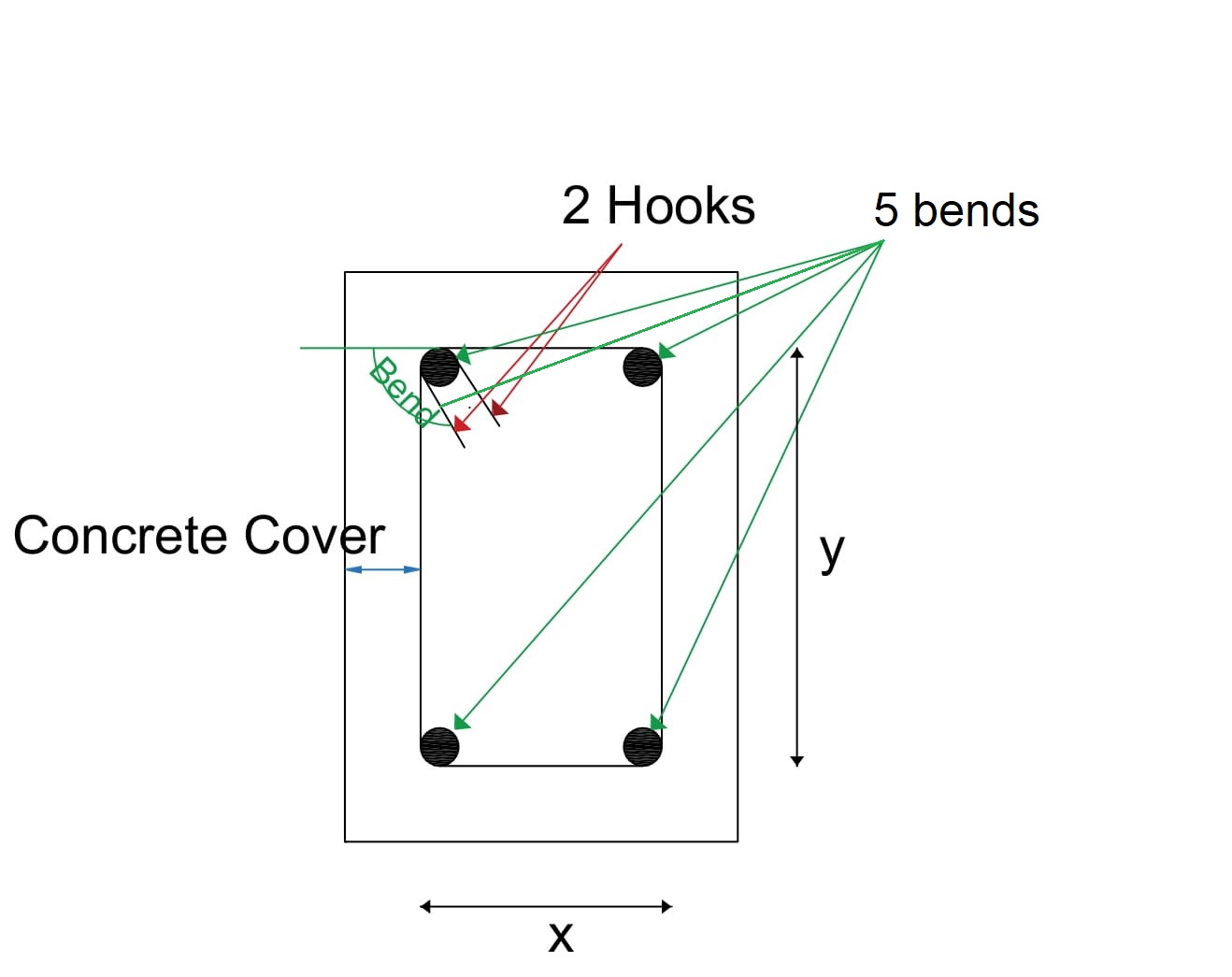
Refer the below image of the typical diagram of stirrup for clear understanding about x & y length, bends, hooks, and concrete cover.
typical stirrup diagram
In the above image, there are 5 bends at 4 corners, 2 hooks, and concrete cover around the stirrup.
x = length of the stirrup in the x-direction after deducting concrete cover &
y = length of the stirrup in the y-direction after deducting concrete cover.

Important standards used in Bends & Hooks:

The below standards are most important in calculating the hook length and bend lengths at corners while finding the cutting length of stirrups.
  • 1 Hook length = 9d or 75mm
  • 45° Bend length = 1d
  • 90° Bend length = 2d
  • 135° Bend length = 3d
Remember, d = Diameter of Bar

Cutting length for Rectangular Stirrups:-

The rectangular column or rectangular beam is the most commonly used shape of the column in any construction. In this shape of beam or column, a rectangular stirrup is usually adopted.
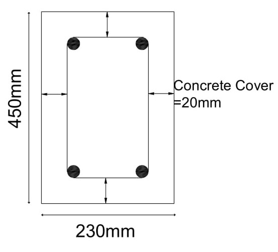
  1. Considering the below Rectangular column size 230mm x 450mm for calculation purpose
    rectangular column details
  2. Adopting Dia of Bar used for stirrups is 8mm
  3. Deducting the concrete cover 20mm from all sides
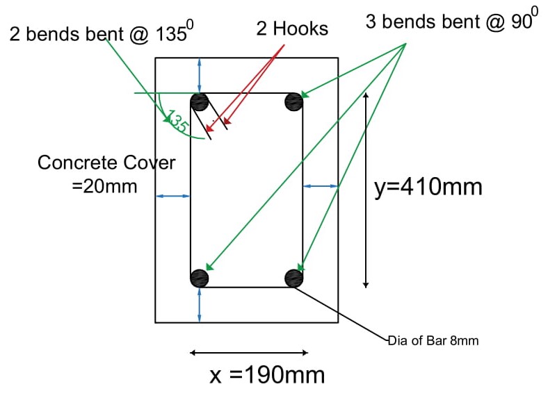
    x = 230 – 20-20 = 190mm
    y = 450-20-20 = 410mm
    cutting length of rectangular stirrup
  4. Total Length of the hooks:
    From fig, There are two hooks which mean 9d+9d = 18d
  5. Total Length of Bends:
    From above fig, There are 3 bends which are bent at an angle of 900 and two bends are bent at an angle of 1350
    Total bend length = 3 x 900 Bend length + 2 x 1350 Bend length = 3 x 2d + 2 x 3d = 12d = 12 x 8 = 96mm
Total Cutting length of Rectangular Stirrup = Perimeter of Rectangle + Total Hook length – Total Bend Length
= 2 (x+y) +18d – 12d = 2(190 + 410) + 18 x 8 – 12 x 8 = 1248mm = 1.248m

Cutting length for Square Stirrups:-

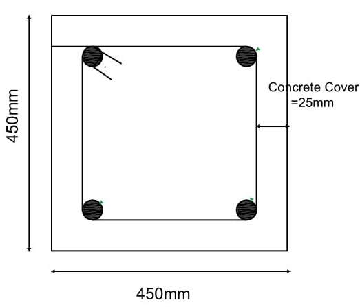
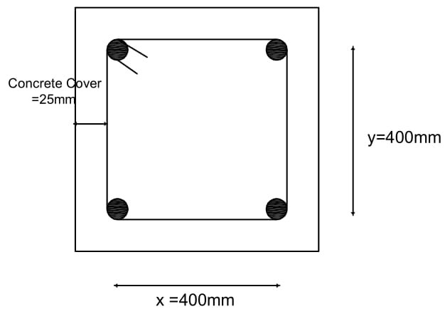
  1. Considered the column size as 450mm x 450mm
    square stirrup details
  2. Adopting Dia of Bar used for stirrups is 8mm
  3. Deducting the concrete cover 25mm from all sides (in the square all sides are equal)
    x = 450- 20-20 = 410mm
    y = 450-20-20 = 410mm, Hence x = y (in square all sides are equal)
    Square stirrup deductions
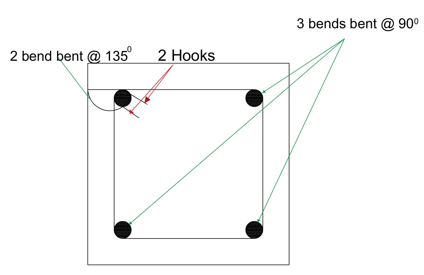
  4. Total Length of the hook:
    There are two hooks which mean 9d+9d = 18d
  5. The total length of Bends:
    There are 3 bends that are bent at an angle of 900 and one is bent at an angle of 1350.
    Total bend length = 3 x 900 Bend length + 2 x 1350 Bend length = 3 x 2d + 2 x 3d = 12d = 12 x 8 = 96mm
    square stirrup details
Total Cutting length of Square Stirrup = Perimeter of Square + Total Hook length – Total Bend Length
= 4 x 410 +18d – 12d = 1648mm = 1.64m

Cutting Length for Circular Stirrup:

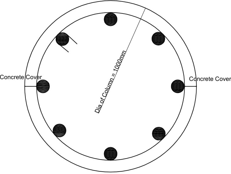
  1. Considered the column dia as D = 1000mm
  2. Adopting Dia of Bar used for stirrups is d =8mm
    Circular Stirrups details
  3. Deducting the concrete cover from diameter of column
    D = 1000-25-25 = 950mm
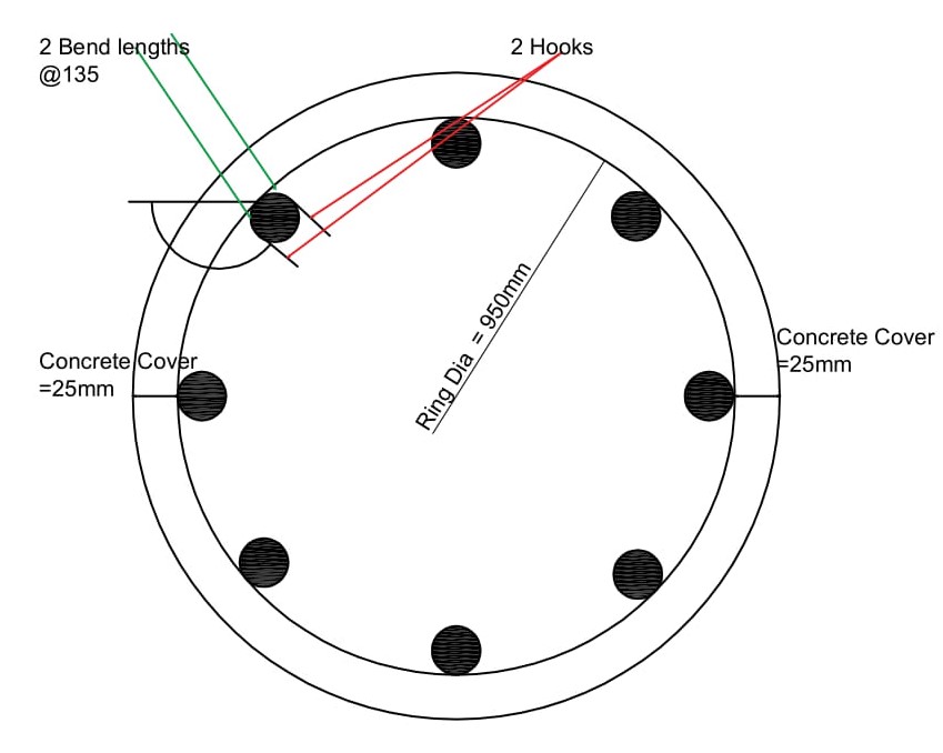
    circular stirrup with hooks and bends
  4. Circumference length of Ring = πD = 950 x 3.14 = 2983mm
  5. Total Length of the hook:
    There are two hooks which means 9d+9d= 18d
  6. Total Length of Bends:
    There are 2 bends which are bent at an angle of 1350
    Total bend length = 2 x 1350 Bend length = 2 x 3d = 6d= 6 x 8 = 48mm
Total Cutting length of Circular Stirrup or Ring = Circumference of Circle + Total Hook length – Total Bend Length= 2983 +18d – 6d =3079mm =3.07m

Cutting Length for Triangular Stirrups:

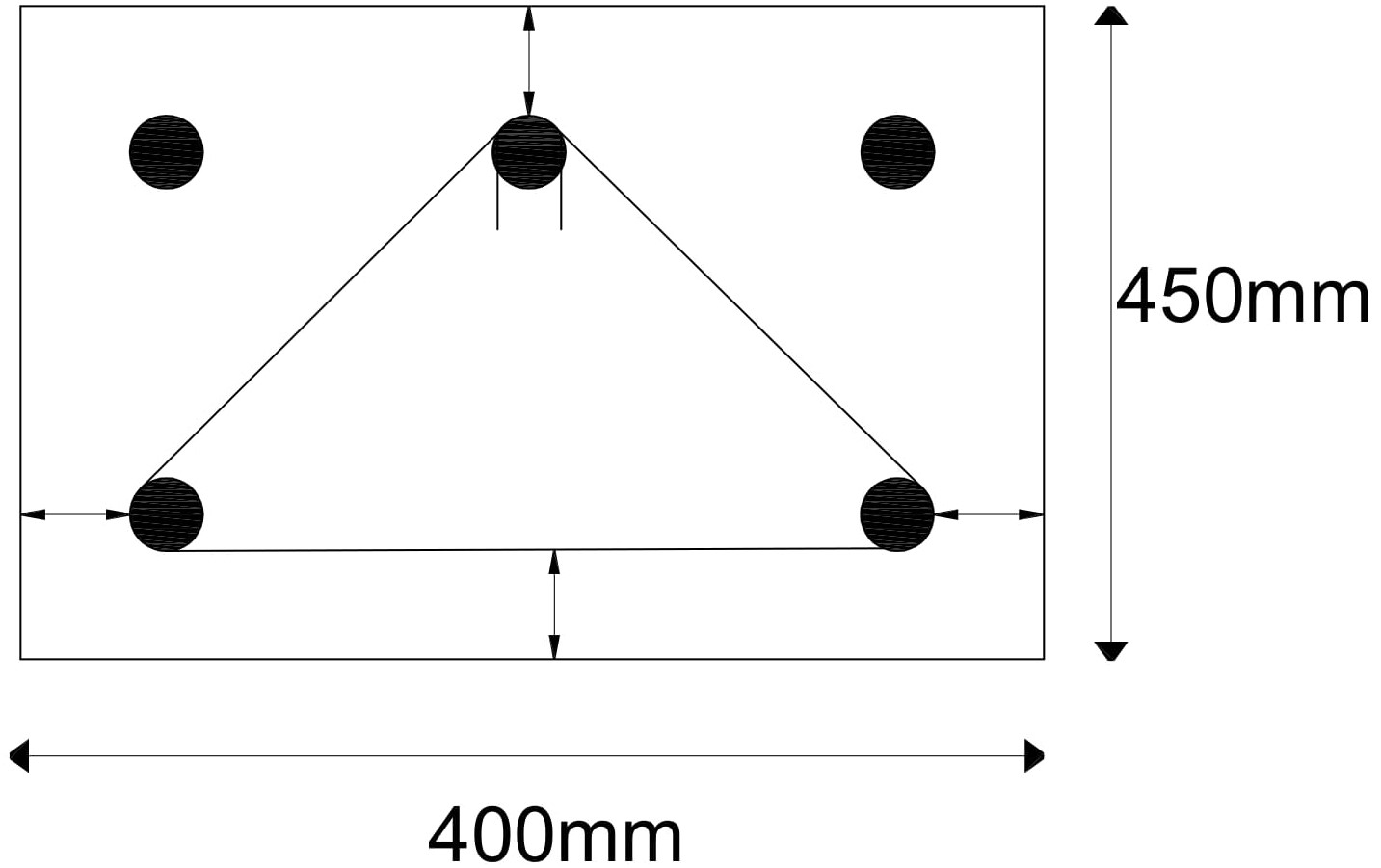
  1. Considered the Column size 400mm x 450mm
    traingular stirrup details
  2. Adopting Dia of Bar used for stirrups is d = 8mm
  3. Deducting the concrete cover 25mm from all sides
    x = 400-20-20 = 360mm
    y = 450-20-20 = 410mm
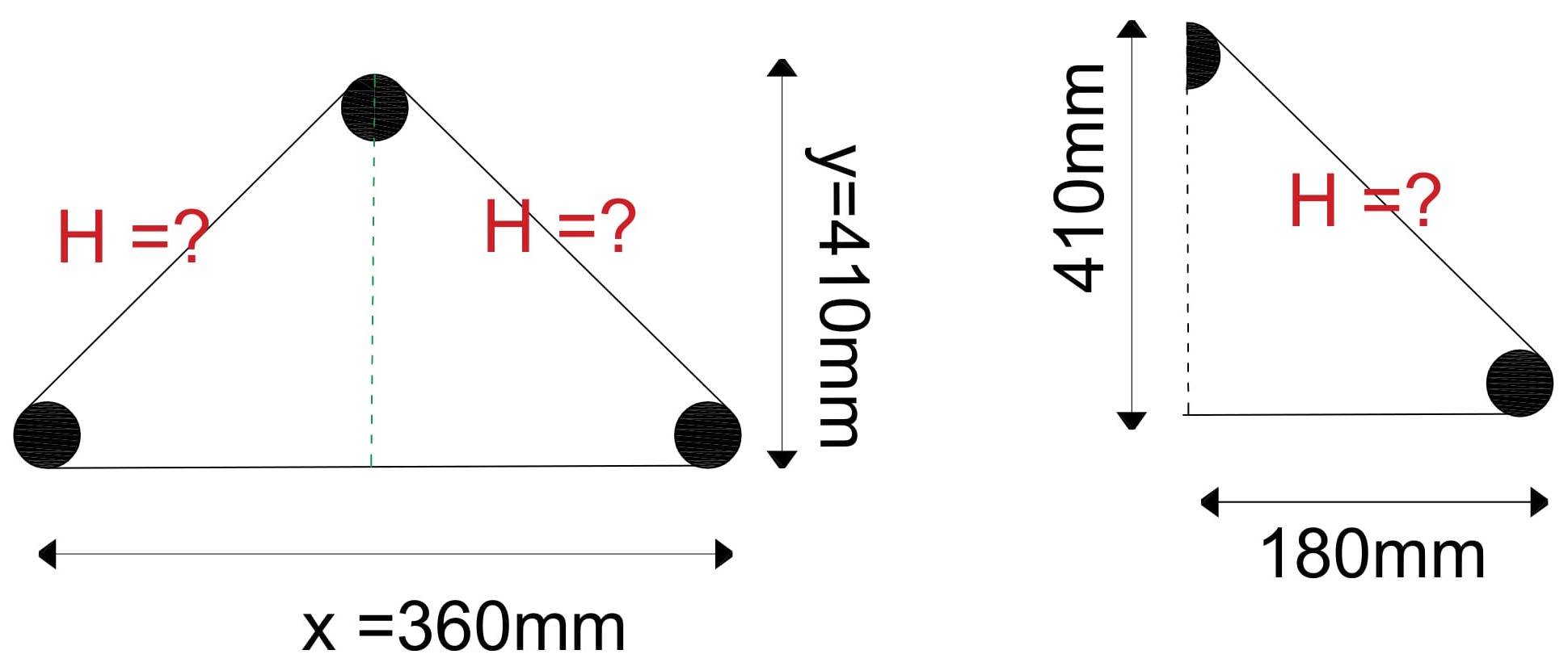
    From Pythagorean theorem,
    Hypotenuse2=(Opposite)2 + (Adjacent)2 
    finding hypotnuse in triangular stirrup
    look at 2nd triangle in above image
    H2=(x/2)2 + y2
    H2=1802 + 4102 => =  √(447)2  = 447mm
    The total length of stirrup till now = 2 x H + 360 = 2 x 447 + 360 = 1254mm
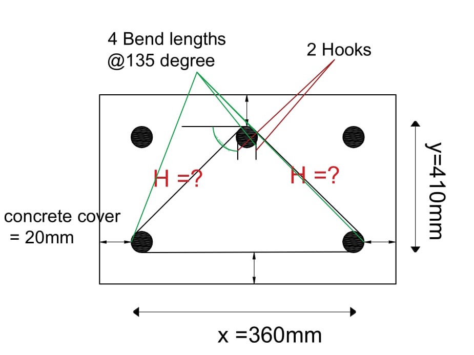
  4. Total Length of the hooks: 
    There are two hooks which means 9d+9d= 18d
    Triangular stirrup Hooks and Bend Lengths
  5. Total length of Bends:
    There are 4 bends which are bent at an angle of 1350
    Total bend length =4 x 1350 Bend length=  4 x 3d = 12d= 12 x 8 = 96mm
Total Cutting length of Triangular Stirrup = Perimeter of Triangle + Total Hook length – Total Bend Length
= 1254+18d – 12d = 1302mm = 1.3m

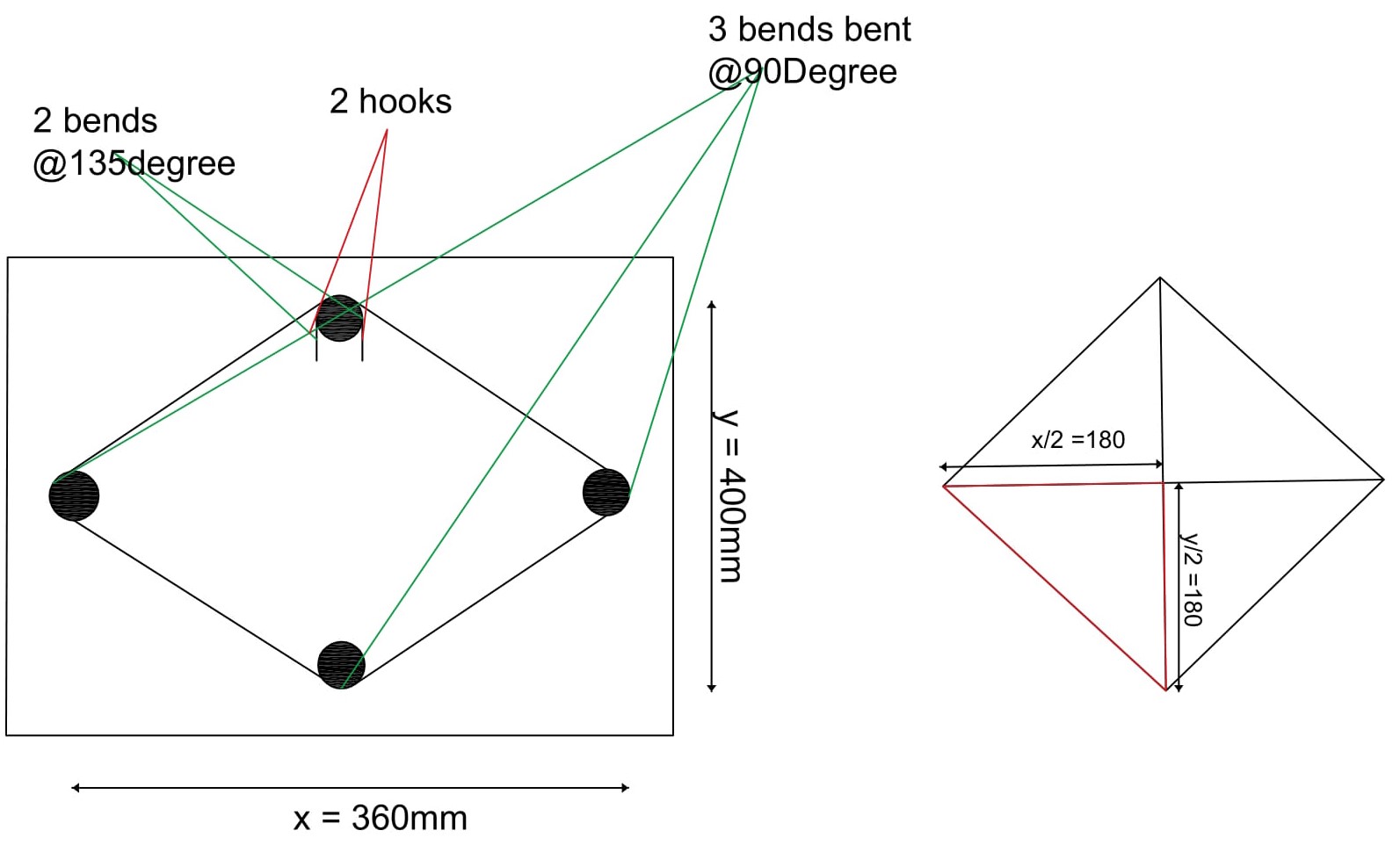
Cutting Length for Diamond Stirrups:

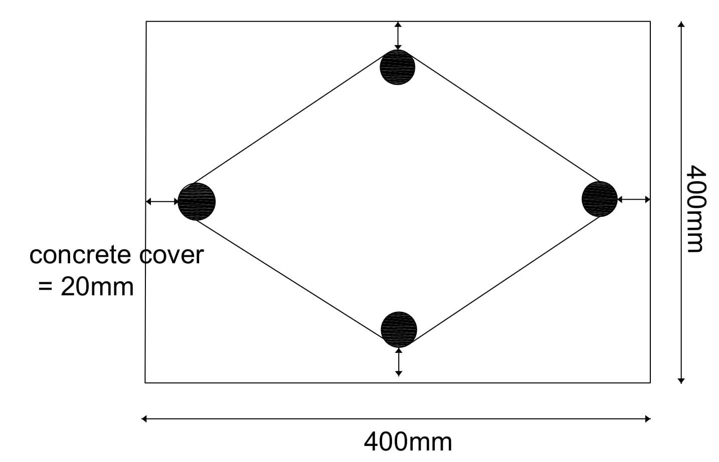
  1. Considered the Column size 400mm x 400mm
    diamond stirrup details
  2. Adopting Dia of Bar used for stirrups is d = 8mm
  3. Deducting the concrete cover 25mm from all sides
    x = 400-20-20 = 360mm
    y = 400-20-20 =360mm
    diamond stirrups hook length and bend length
    From Pythagorean theorem,
    Hypotenuse2=(Opposite)2 + (Adjacent)2 
    H2=(x/2)2 +( y/2)2
    H2=1802 + 1802 => =  √(254)2  = 254mm
  4. The total length of stirrup = 4 x H  =4 x 254 = 1016mm
  5. Total Length of the hook:
    There are two hooks which means 9d+9d= 18d
  6. Total length of Bends:
    There are 3 bends which are bent at an angle of 90 + 2 bends which are bent at an angle of 1350
    Total bend length = 3 x 900 Bend length + 2 x 1350 Bend length= 3 x 2d + 2 x 3d = 12d = 12 x 8 = 96mm
Total Cutting length of Diamond  Stirrup = Perimeter of Diamond shape + Total Hook length – Total Bend Length= 1016+144-96 = 1064mm = 1.064mm
I hope now you can easily find the cutting length for different types of stirrups.

Principle of Dumpy Level Instrument:


Principle of Dumpy Level Instrument:

The dumpy level operates on the principle by establishing a visual relationship between two or more points, through an inbuilt telescope and a bubble level. The desirable level of accuracy can be achieved through steps.
It is also called through various names such as Surveyors levels, Builders level, Dumpy level, or even its pre-historic version “Y(Wye) Level”.

Accuracy of Dumpy level over other leveling instruments:

The prime reason for using the Dumpy level over other leveling instruments is its accuracy.
A dumpy level is known for high accuracy values for most of the Tacheometric methods. The accuracy of a dumpy level can be within 1:4000  for every 100 m.

Use of Dumpy level in Surveying:

Dumpy level holds significant importance in the surveying of a construction site. The level of accuracy and handiness of the dumpy level has made it a prominent choice amongst surveyors.
  • The prime reason for performing leveling on a construction site is to make the field level and even.
  • To determine the differences in height between two points.
  • To measure the height and distance of different locations of surveying land through the principle of relativity.
  • To measure the following distance amongst various points on the surveying land.
  • Setting out levels and inclined surfaces for construction.
  • To draw contours on land.

Important Components of Dumpy level:

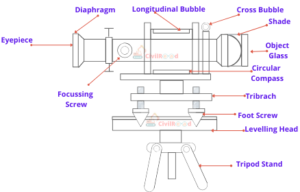
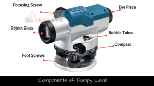
Dumpy Level Components
Parts of Dumpylevel

1. Telescope:-

The telescope is used to measure distant objects in the line of sight. The telescope is generally connected with vertical spindle, facilitating telescope to be movable in various directions.
Telescope comprises of various parts, all the parts are described below.
  • Eye Piece: It comprises of a magnifying glass and is primarily used by the observer.
  • Objective Piece: it is placed at the farther end of eyepiece. It comprises a convex lens and a concave lens.
  • Diaphragm: Provided in the outline of the eyepiece with the cross of dark metal. They are provided to the bisect object.
  • Focusing Screw: They are meant to align the focus and image clarity of the object.
  • Ray Shade: Prevents sunlight from entering the objective lens.

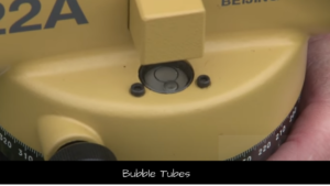
2. Bubble Tubes

They are provided to align the level of instrument. Provided by bubble tubes on horizontal and vertical direction. The instrument is ready to survey when both the bubbles are in the center.

3. Compass

It is used to determine the magnetic bearing of the line of the path of the survey. The compass comprises a pointer on marking of directions. The compass is aligned for the magnetic bearing in the north direction.

4. Vertical Spindle

Located at the center of the instrument. It helps the telescope to rotate in the vertical direction. Vertical Spindle is meant to be a conjunction point between tripod and telescope.

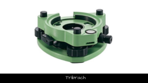
5. Tribrach

It is parallel to the leveling head and primarily utilized to adjust the horizontal level of the instrument. The trivet is connected through foot screws.
Tribrach in Dumy Level

6. Foot Screws

The foot screws are used to calibrate the instrument through the bubble tube. Adjusting foot screws one can calibrate the tribrach plate. To ensure the bubble is at the center, foot screws are operated.

7. Leveling Head

Also known as a trivet, it comprises of two triangular plates aligned parallel to each other. Comprises of groves to hold foot screws.

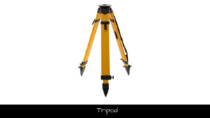
8. Tripod

Tripod is the supporting medium of the complete dumpy level. Comprising of three legs made of hollow steel sections or light or hardwood. Steel shoes provided at the foot ensures that the tripod is immobile with slight jerks.
Tripod for Dumpy level

The procedure of surveying on Dumpy Level:

The step by step procedure to perform the surveying using Dumpy level. Survey through a dumpy level can be easily conducted over a site. The dumpy level is a two-man procedure, one may require at least an assistant to proceed with the operation. Below listed types of equipment are the ones that one requires to initiate the surveying operation.
  • Dumpy Level
  • Tripod with foot screws.
  • E-meter Staff/ English Staff
Once the above instruments are available, the surveying operation can proceed. The following steps need to be followed to complete with the surveying operation.

Setup a Benchmark [BM]:-

The process of surveying starts from a specified benchmark with already known height concerning Mean Sea Level (MSL). This previous data of benchmark can be acquired from previous surveys. Benchmark data is usually found on churches, govt buildings, municipal offices, Railway station boards, etc. If data is not available, one may choose an arbitrary point (temporary benchmark like a fence post, etc) with an assumed height.
You can look up the benchmarks of your location from here 
Railway Board for Benchmark
In the above Railway Board, you can see the Mean sea level is mentioned.

Location and Position of Dumpy level:

Select a place where you have a clear sight of the benchmark. It is recommended to set up the instrument in the center of the land where you can see all the site including the benchmark.

Setting up Dumpy level on Tripod:-

The Tripod has to be placed firmly on the ground so that it can efficiently hold the dumpy level. In general, the tripod height must be adjusted up till eyesight. One must ensure the legs of the tripod stand are wide enough to hold the instrument properly and legs are properly inserted into the ground.
The dumpy level is to be firmly and securely fixed with the tripod stand through the foot screws. One must ensure that the device is tightly fixed with a tripod. Since the level head is very sensitive, and the instrument is very costly, special care should be taken while handling it.
To work efficiently, the Dumpy level must behold in the complete horizontal direction. Foot screws aka Levelling screws could be used to set a leveled condition. The leveling screws must be adjusted until the alignment bubble is aligned in the center of the marking level. To bring the bubble in the center, leveling screws are further adjusted.

Observations and Readings:-

Backsight [BS] Reading:

The first reading which the surveyor needs to take is back sight. Backsight reading helps you to find out the height of the instrument(H.I.). These two readings enable us to proceed with further foresight level readings.  The second man (assistant) should hold the staff “vertically” on the benchmark. The operator begins the surveying operation by viewing through the eyepiece of the telescope and rotate the dump level until the crosshairs are lined up with the E staff. Then look and focus to see the numbers on E Staff. The staff comprises of both metric and imperial measurements. The “E” marking on the staff signifies 5 cm as of metric scale.

Height of the Instrument (H.I.) or Height of the Level: 

To find out the height of the level, you must know the height of the backsight which we have noted in the previous step. Now add the benchmark height to the backsight height which will give you the height of the instrument.
Height of the level = Bench Mark(BM) height + Back Sight Reading

Foresight readings:

After finding the height of the instrument you are now ready to proceed with the foresight readings. Locate and mark the points (A, B, C) on the ground at which you intended to find out the level. Place the E Staff on the selected point (Suppose ‘A’) and hold it vertically. Repeat the same procedure of taking readings from E Staff which we performed to find out the backsight height. Record the readings from E staff and find out the foresight height of (Point ‘A’).

Calculating the Reduced level:

The reduced level is the difference between the Height of the instrument and Foresight reading.
Reduced Level = Height of the instrument – Foresight reading
The results are tabulated in the below table.
Reading No.Identification pointBenchmark HeightBacksightHeight of InstrumentReduced Level
1.
2.
3.
4.
This reduced level gives a report about the quantity of backfill that needs to be added or the quantity of excavation that needs to be done to make the ground even.

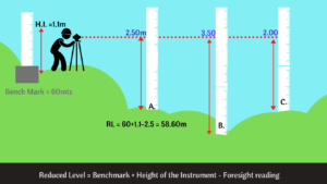
Example:

Dumpy level readings
In the above image, you can clearly understand that the ground is uneven and leveling is a must to construct any structure on this land.
We considered the Benchmark height = 60mts
Height of the instrument = 1.1mts
and the foresight height of point A  = 2.50m
Reduced level =60+1.1-2.5 = 58.60m.
A simple task for you find out the reduced levels of points B and C from the above image and enter your result in comments.

Precautions while setting up Dumpy level:

The dumpy level is all about levels. Necessary precautions should be taken while handling the instrument. If not instrument will go out of level and process inaccurate results.
  • The tripod must be adjusted till eye height.
  • Try to avoid touching or applying pressure on the tripod while moving around.
  • When moving around the tripod, make sure you don't trip over the legs.
  • Keep checking the bubble, minute fluctuation in a bubble gives inaccurate results.
  • Avoid setting up the instrument on soft ground.

Advantages of Dumpy Level:

The dumpy level is amongst the most famous used surveying instrument. The prominent advantages of dumpy level are as follows:
  • Simpler construction with minimum movable parts
  • Minimum adjustments are to be made
  • High rigidity makes it versatile for long-duration surveys
  • High optical power
  • Cost-efficient in terms of usage on diversified construction sites

Limitations of Dumpy Level:

Despite being such a versatile instrument, the Dumpy level even has some limitations. These limitations minimize the application to a certain extent.
  • Limited to the site with horizontal angle measurement
  • There might be a certain level of discrepancies in the values obtained.