CivilHubDesk: Concrete
Showing posts with label Concrete. Show all posts

Wednesday, March 4, 2020

Profometer Test on Concrete Structures: Purpose and Applications


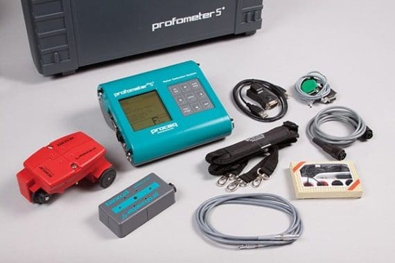
Profometer test is a non-destructive testing technique used to detect the location and size of reinforcements and concrete cover quickly and accurately. A small, portable, and handy instrument which is known as profometer or rebar locator, is used in this test.


The equipment weight is less than two kgs, and works on normal batteries and thus does not require any electrical connection. The basic principle in this test method is that the presence of steel affects the electromagnetic field which is directed by profilometer device.
This instrument is available with sufficient memory to store measured data. Integrated software is loaded in the equipment for carrying out complicated calculations and printing statistical values.
Profilometer test is widely used and has many applications. For instance, it is used to specify reinforcement size, location, and condition of existing structures to evaluate their actual strength, location reinforcement is necessary to be determined prior to drilling and cutting cores for testing concrete, analysis of corrosion, conformity check, and quality assurance.

Purpose of Profometer Test

  1. Assess the location of steel bars
  2. Measure the diameter of reinforcement bars
  3. Evaluate the thickness of the concrete cover.

Principle of Profometer Test

The instrument is based upon measurement of the change of an electromagnetic field which is caused by steel bars embedded in the concrete.

Calibration of Profometer Equipment

Profometer device needs to be calibrated before starting the operations and at the end of the test in order to ensure satisfactory working and to get accurate results. To achieve this purpose, the test block provided with the instrument should be used.
To check the calibration accuracy, the size and cover of the reinforcement of the text block is measured at different locations by using profometer equipment.
Then compare the recorded data with the standard values prescribed on the test block. The recorded data and the standard values should match.

Profometer Test Instrument and Accessories
Fig. 1: Profometer Test Instrument and Accessories

Test Preparations

There are certain preparations that are required to be done before the testing operation begins. For instance, it is essential to conduct a proper assessment of the structure before the test.
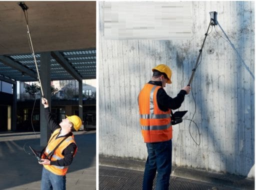
For this purpose, proper staging, ladder or a suspended platform may be provided. Before actual scanning, marking is done with chalk on the concrete surface by dividing it into panels of equal areas.

Profometer Test Procedures1. Determine Steel Bar Location

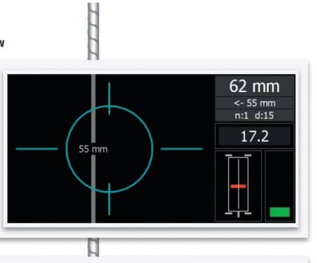
Path measuring device and spot probes are used together for path measurements and scanning of rebars. These are connected to profometer via cables and are moved on the concrete surface for scanning the rebars and measuring the spacing. As soon as the bar is located, it is displayed on the screen. Once the bar is located, it is marked on the concrete surface.

Detect Rebar Location
Fig. 2: Detect Rebar Location

2. Measure Bar Diameter

The diameter probe is used for measuring the diameter of bars. It is also connected with profilometer by a cable. After finding out the location of rebar, the diameter probe is placed on the bar parallel to the bar axis. Four readings are displayed and the mean value of these readings is taken as the diameter of the bar.

Diameter of Rebar
Fig. 3: Diameter of Rebar

3. Determine Concrete Cover

The depth probe of the profilometer is used to measure the cover. It is also connected with a profilometer by cable and is placed exactly on the bar. As soon as the depth probe is above rebar or nearest to it, it gives an audio signal through a short beep and visual display. Simultaneously, the measured concrete cover is stored in memory.

Precautions

There are various factors that affect Profometer results. These factors should be considered in the interpretation of observations obtained from this instrument:
  1. Arrangement of reinforcement,
  2. Variation in the iron content of cement and use of aggregate with magnetic properties,
  3. Metal ties also affect the magnetic field.

Advantages and Limitations

This is a purely non-destructive test for the evaluation of concrete structures, particularly old structures.
  • The method is very fast and gives quite accurate results if the reinforcement is not heavily congested.
  • The equipment is very light and even one person can perform the test without any assistance.
  • Factors such as very closely spaced bars or bundled bars, binding wire, aggregate containing iron or magnetic properties would affect the accuracy of the measurements.
  • Concrete cover thickness may be underestimated when special cement, including high alumna or added pigments, are used.
  • Rebars in excess 32mm distance may require recalibration.

Applications

1.Evaluate the Strength of Concrete Structures
Profilometer test can be used to evaluate the actual strength of concrete structures in which the number of reinforcing bars, their condition of corrosion, concrete cover, and grade of concrete are required.
In the case of old structures, when the detailed drawings are not available, it becomes very difficult to compute the strength of the structure which is required for the strengthening scheme of the structure.
Sometimes, the strength of concrete structures is to be checked to permit higher load and in the absence of reinforcement details, it becomes very difficult to make a decision.
2. Corrosion analysis
3. The method can be used both for quality control as well as quality assurance of new structures.
4. Locating rebars is a necessity when drilling, cutting coring as well as a preliminary operation required for most other non-destructive investigations.

Testing Concrete Structures
Fig. 4: Testing Concrete Structures

How to calculate the shuttering area? Learn about shuttering.


Shuttering:

Shuttering is an arrangement done for vertical surfaces to support the wet concrete till it attains the desired strength. Shuttering is a part of formwork. Follow below to know how to calculate the shuttering area.


 Calculating Shuttering area:-
The shuttering is calculated in terms of Sq.M in the Rate Analysis of Shuttering. In order to calculate the area of shuttering you must know how to calculate the peripheral length (Perimeter) of any shape.
Peripheral length (Perimeter):
Perimeter is the distance around a two-dimensional shape.
For example square has four sides determine one side length is “s”
then peripheral length = s+s+s+s = 4s
Important Formulae for Calculating Shuttering Area:
§  The perimeter of Square: 4S  (S = Length of Side)
§  The perimeter of Rectangle: 2[L+B]  (L=Length & B = Breadth)
§  The perimeter of Circle: 2πr  (r = Radius of circle)
§  Area of Rectangle = Length x Breadth
§  Area of Square = Side x Side
Remember, each member in a structure either it may be Slab or Beam or Column it has six sides (faces). The shuttering area can be calculated by using two methods. One is by below-mentioned formula and another method is by calculating the individual areas of faces. To keep it clear, I used both the methods in this article.
Formulae of Shuttering Area:

Shuttering area = Peripheral length (Perimeter) x Depth

Calculation of Shuttering Area of a Column:

Consider a column as shown in the below figure. To calculate the shuttering area follow the below steps:-


For Column, shuttering is done for four sides and the other two sides (the top of the column is left for filling concrete and bottom is fixed to ground level). Neglect the top and bottom in the calculation.
The side of the column is in rectangle shape with side length “l” and breadth “b”
Peripheral length of Rectangle is   = l+b+l+b = 2l+2b
Shuttering area = Peripheral length (Perimeter) x Depth
Peripheral length = 2×0.8+2×0.6 = 1.6+1.2 = 2.8Sq.m
Total Area of Shuttering of a column  = 2.8 x 4 = 11.2 Sq.m
In case, the shape of the column is Circular then the below-mentioned formulae is used for calculating the shuttering area
Shuttering area of Circular Column = 2πr x Depth 

Calculation of Shuttering Area of a Beam:

For calculation purpose, I am considering the beam as shown in figure:

For Beam, shuttering is done in 5 sides and the other side (top the side is left to fill concrete)
Shuttering area can also be calculated by finding out the individual area of each faces as below:
Face 1 : Area of rectangle = L x B = 0.8 x 4 = 3.2
Face 2 : Area of rectangle = L x B = 0.6 x 4 = 2.4
Face 3 : Area of rectangle = L x B = 0.8 x 4 = 3.2
Face 4 : Area of rectangle = L x B = 0.8 x 0.6 = 0.48
Face 5 : Area of rectangle = L x B = 0.8 x 0.6 = 0.48
Total Area of Shuttering = 3.2 + 2.4 + 3.2+ 0.48 +0.48
= 9.76.Sqm

Calculation of Shuttering Area of a Slab:

Slab rests on beam, there is no need of providing shuttering to the slab on four sides.  Same as beam & column, the top of the slab is left to fill concrete and for curing. Hence, shuttering is only provided to the bottom of the slab. The below-mentioned values are considered for finding the shuttering of a slab.

Shuttering area of Slab = Bottom area of slab = L x B
Bottom Area = 5 x 4 = 20 Sqm


Saturday, February 29, 2020

How to check the quality of cement on site

Quality of cement on site:

Cement is the most used material in any construction. It acts as a binder that binds aggregate and sand together in concrete. Well, there are so many theories explained how to check the quality of cement in the lab but most of them require huge apparatus to check the quality of cement.
It is not easy to check all properties of cement on the site but there exist some preliminary field tests which can give us a rough idea about the quality of cement.
Below mentioned tests are the simple tests that you can perform easily on-site to find out the quality of cement with no apparatus. These preliminary tests include checking the properties of cement which affect the Cement strength and quality.

1. Date of Packing (MFG Date):

Several studies stated that as the Strength of cement reduces as time goes on. As per IS Specifications cement should be re-tested if it is stored more than three months in the mill.
The below table gives details about the percentage of strength loss for different time intervals.
Age of cementPercentage of Cement Strength reduction
3 months20%-30%
6 months30%-40%
12 months40%-50%
From the above table, it is clear that the strength of cement loses its strength over a period of time.

2. Colour of Cement:

The color of the cement should be uniform. An ideal color of cement is grey with a light greenish shade. Cement color gives an indication of excess clay or lime.
quality of cement on site

3. Check for lumps:

Lumps are formed due to the presence of moisture in cement. Cement undergoes a chemical reaction when it is reacted with the atmospheric moisture this process is termed as hydration. Moisture is a big enemy for cement. Cement becomes useless once it is hydrated with water (liquid form or vapor form)


4. Rubbing Test:

Take a pinch of cement rub within your fingers, it should feel smooth while rubbing. If it is rough, it indicates that cement is mixed with sand.

5. Float test of cement:

Take a handful of cement and throw it in water, good quality of Cement should sink and should not float on water.

6. Hand insertion:

Insert your hand into the cement bag. It must give you a cool feeling. It implies that the no hydration reaction taken place in cement bag,

7. Shape test of cement:

Cement is also named as Hydraulic Cement as it also sets underwater.
Take a 100g of cement and make a stiff paste by adding some water. Then prepare a cement cake with sharp edges and place it on a glass plate. Immerse this plate in the water bucket. Observe that the shape shouldn’t get disturbed while settling. A good cement should be able to set and attain strength in water.

8. Strength test:

Make A block of cement 25 mm x 25 mm and 200 mm long. Immerse the block in water for 7 days. Place the immersed block on supports 15000 mm apart and then load with a weight of 340 N. the block which is made of good cement should not show any sign of failure.

9. Specific Gravity of cement:

Finding specific gravity of cement is of utmost importance if cement is stored for more than three months. A good cement should have Specific gravity (Sg) in between 3.1-3.6g/cc. For more details on test procedure of specific gravity refer here

What Is Dowel Bar – Its Purpose, Use And Advantages

What Is Dowel Bar?

Dowel bar is a short round, smooth steel bar used to provide a mechanical connection between slab without restricting horizontal joint movement. These bars are mainly used in jointed plain concrete pavement (JPCP) to carry additional stress and load-induced due to the moving vehicle.

Purpose Of Dowel Bar:
Dowel bars are used
  • To transfer the load from one slab to its adjacent slab such that two consecutive slabs move together and reduce impact loading developed by the slabs by their independent movement.
  • To reduce joint faulting and corner cracking.
  • To improve the performance of pavement joints.


The size of dowel bars depends on the thickness of the pavement. Usually, dowel bars are 18 inches (460mm) long, 1.25 to 1.5 inch (32 to 38 mm) in diameter, and spaced 12 inches (305mm) apart. T0 protect the bars from corrosion dowel bars are either stainless steel or epoxy coated.


dowel bar
Epoxy Coated Dowel Bar
Dowel bars are placed across transverse joints of concrete pavement to allow movements. They are inserted at the mid-depth of the slab and coated a bond breaking material to restrict bonding to the PCC. Thus dowels help to transfer loads allowing expansion and contraction of adjacent slabs independently.


dowel bar
Dowel bars must be placed parallel to the centerline. New channels must be cut so that at least one-half dowel can be on each side of the joint or crack.


Advantages Of Dowel Bars:

  • Reduces deflection and stresses.
  • It increases the load-carrying capacity of slabs.
  • It increases the initial pavement life.

Installation:

  • Dowel Baskets.
  • Dowel bar inserter (DBI).
  • A bond breaker (usual grease) must be applied prior to placement.

Installation Problems:

  • Bars are missing or misplaced due to poorly adjusted equipment, damaged dowel baskets, or improper basket anchoring.
  • Concrete around the bars is poorly compacted or too stiff mix is used.

Note:
Dowel bars are also used in the RCC wall for slabs and columns. They are placed in two ways:
Method 1: Short length bar placed before pouring concrete in position. It is the most common and successful method in terms of bonding, cost-effective as it doesn’t require chemical for bonding purposes.
Method 2: Drilling hole in the concrete, and putting Hilti chemical for strong bonding. It is expensive as Hilti chemical is used which is costly. This method is adopted when we forgot to place extension bars before concreting.

Wednesday, February 26, 2020

Concrete Repair (a practical guide)


Personally, I love Books. There are those that make you think, make you laugh, motivate and inspire you. Below you'll find more of our best Books under Books tab and if you can't find it please comment the name and subject of the Books and I'll add it from my Online Library. Please give me your feedback. thanks in advance

Monday, February 24, 2020

Rat Trap Bond – Construction, Advantages, and Disadvantages

Rat trap bond is a modular type of masonry bond in which the bricks are placed in a vertical position which creates a cavity in the wall while maintaining the same wall thickness as that of the conventional brick masonry wall. It is also known as a Chinese brick bond.

The purpose of using this type of masonry bond is to reduce the number of bricks and mortar required as compared to the English/Flemish bond because of the cavity formed in the wall.

Fig 1: Rat Trap Masonry.

Architect Laurie Baker introduced it in Kerala in the 1970s and used it extensively for its lower construction cost, reduced material requirement and better thermal efficiency than conventional masonry wall, without compromising the strength of the wall.

In this article, we discuss the material criteria, construction, advantages, and disadvantages of rat trap bond masonry.
Selection of Bricks

The criteria that are set for the selection of bricks is of utmost importance as less number of bricks are used in the construction of rat trap masonry.

The size of the bricks used must be of a standard size and variation in size is not accepted. The acceptable sizes of brick in Indian scenarios are – Length 220-250 mm, Width 100-115mm and Height 65- 75mm.
The edges and corners of the bricks must be straight and sharp and perfectly rectangular in size.
Having a uniform size of bricks is important as the masonry is the modular type and to achieve good strength and finish.

Table 1: The material strength requirement Rat Trap Bond


Type of Construction

Recommended Compressive Strength of Bricks Best Practice Minimum Allowable

Recommended Mortar Ratio


Load bearing, Double storied


40 – 50 kg/cm2

1:5

Load bearing, Single storied

35 – 40 kg/ cm2

1:4


Infill masonry in frame structure,
no restriction on number of floors

Min 35 kg/ cm2

Not less than 1:4

Construction of Rat Trap Bond
The bricks are placed in a vertical position so that 110 mm face is seen from front elevation, instead of the 75mm face (considering brick of standard size 230 X 110 X 75 mm).
As the width of the wall is kept as 230mm, a cavity is created inside the wall.
However, the first and the last layer of the masonry is constructed as the convention sold masonry.
In the sill, lintel and sides of openings are made of solid masonry (without cavity) for fixing of frames.
To strengthen the masonry, vertical and horizontal reinforcement bars are provided in the cavities.
Electrical conduits and plumbing pipes, with prior planning, can be put inside the cavity for better aesthetics.

Fig 2: Construction of Rat Trap Bond

Image Courtesy: ArchitectureLive!
Advantages of Rat Trap Bond
The cavities in the masonry act as thermal insulators. Thus, the interiors remain cooler in summer and warmer in winter.
Rat Trap masonry uses fewer bricks and mortar reducing the cost of masonry up to 30% when compared with conventional brick masonry.
The number of bricks used in the construction of rat trap masonry is 470, whereas, in conventional masonry, it is 550.
Walls constructed using rat trap masonry can be used as load-bearing as well as a thick partition wall.
Rat-trap bond when kept exposed, creates aesthetically pleasing wall surface and the cost of plastering and painting may also be avoided.
As this type of masonry has 30% of cavities, the dead load of the structure is reduced which in turn reduces the structure supporting members such as column and footing.
In case of more structural safety, reinforcement bars can be inserted through the cavity until the foundation.
Many buildings that were constructed decades ago have proved that this type of walling technology is durable and the maintenance costs are low.
Disadvantages of Rat Trap Bond
Due to the formation of cavities in the masonry, the building does not provide good sound insulations.
Skilled labor is required to construct this type of masonry.
Frequent cleaning of external surface required if not plastered.
Special care and attention to be given while designing and constructing rat trap bond masonry.

Travel everywhere!

Ads 970x90