Civilhubdesk.com: construction
Showing posts with label construction. Show all posts

Saturday, March 7, 2020

Calculation of Safe Bearing capacity of soil on site | SBC Values for Different Soils

Safe Bearing Capacity of Soil:

The First test which one should be performed before construction is the safe bearing capacity of the soil. It’s a preliminary test that should be conducted before the construction of any structure. It is recommended that the safe bearing capacity of soil should be tested at all the points of footings.

What is a Safe Bearing Capacity of Soil?

A safe bearing capacity of soil field test is done to check the capacity of the soil to withstand loads. Let us consider an example of a small plastic chair, This small plastic chair is made for kids and It can bear a capacity of 10 Kgs. Suppose, if an adult sat on it, then Chair will be broken. The same case is applied to the soil, If more load is applied on soil than its resistance, then soil starts displacing or breaking which leads to settlements. In order to keep the structure safe, the Safe bearing capacity of a soil is calculated on the field at different points and the selection of footing is done accordingly.
The maximum load per unit area which the soil can bear without any displacement or settlements is designated as the “Safe bearing capacity of the soil.”

Safe Bearing Capacity of Soil formula:

Safe Bearing Capacity of Soil Formula

Ultimate Bearing Capacity of Soil:

The point at which soil starts displacing is called the Ultimate bearing capacity of the soil.
For Example: Take a rubber band and stretch it oppositely, Rubberband has an elastic property which it can regain back to the original position. If u start stretching it more, it may break at a certain point, that point is known as the Ultimate point of Rubberband where it loses its elasticity and it won’t come back to its original position.
rubber band theory
The same can be applied to the soil, Soil has an ultimate bearing capacity where it can bear the load up to a certain point. After that point, Soil starts displacing (Settlements). That point is called as Ultimate bearing capacity of the soil.
The ultimate bearing capacity of soil varies with the type of soil and the atmospheric conditions.
The factor of Safety depends upon the type of construction and it usually ranges between 2 and 3. For High rise constructions, we go with F.O.S 3.

Safe Bearing Capacity of Soil Testing Procedure:

Well, so many theories explained how to find the safe bearing capacity of the soil. Among them, the Drop weight method is the easiest and reliable test.
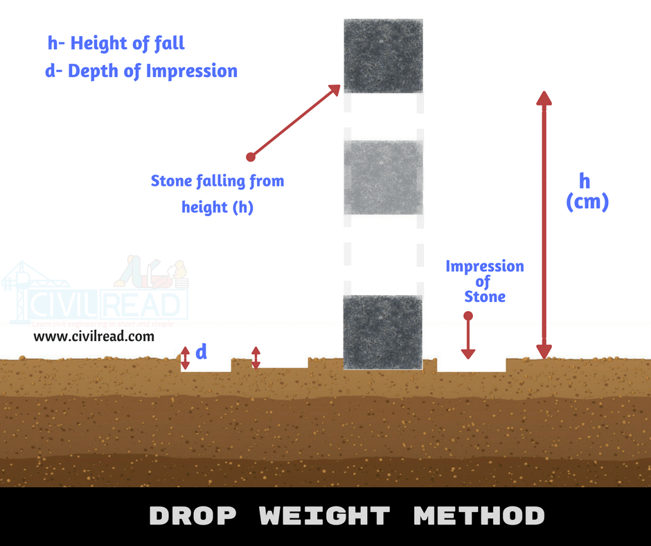
Drop weight method:

This method is the field test for the Safe bearing capacity of the soil.
  1. Firstly Excavate a pit of required depth. (preferably equal to the depth of foundation)
  2. Take a square cube of known weight and dimensions.
  3. Now drop the square-cube on the pit with a known height.
  4. Measure the impression made on the pit by square cube using the scale.
    (For accurate results, Drop the cube several times on the same pit and calculate the average depth of Impressions “d”.)
drop weight method - Soil bearing capacity

Example:

Weight of Cube = 0.6Kg, Height of fall = 120cm
Depth of impression = 0.8cm;
Cross Section Area (A) = 20cm2; Factor of Safety=2
Ultimate Bearing Capacity [UR] = [0.6 x 120]/0.8 = 90Kg
Safe Bearing Capacity of Soil = 90 / [20 x 2] = 2.25Kg/cm2

Why calculate the Safe bearing capacity of the soil before starting construction:

Liquefaction
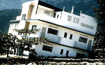
From the above figure, it is clear that the building is fallen on only one side. It is occurred by the settlements on one side of the building, due to this the building is overturned on one side but didn’t collapse.
The reason for this is The safe bearing capacity of the soil is enough at one part of the building, but not the other part. It is recommended to check the SBC of soil at all footing positions to overcome the Soil Liquefaction.  And the perfect type of footings is chosen by checking the Safe bearing capacity of the soil.

Safe bearing capacity (SBC) Values for different types of soils:

These are probable values that are only used only for preliminary design. The actual safe bearing capacity of the soil is calculated by using IS mentioned Codes.

Must-Have knowledge for Civil Engineers | Civil Engineering Tips


There are many activities that should be performed by civil engineers at the site and in the lab. Here we are going to discuss some important points which every civil engineer must learn and remember. These tips can also help to crack the interview. This is a kick start guide if you are joining in any company as a Civil engineer.


Civil Engineering Tips:

  • ASTM Abbreviation: American Society for Testing Materials
  • Grade of Concrete is denoted as Cement: Sand: Aggregate (Ex M20 Grade : 1:1.5:3)
  • C/C means Center to Center Distance
  • DL means Development Length
  • Lapping of bars not allowed if the dia of the bar is more than 36mm.
  • For circular column minimum of 6 longitudinal bars are used.
  • The minimum thickness of the slab is 0.125m
  • A water pH value of less than 6 should not be used for construction purposes.
  • The concrete Should not be thrown from a height of more than 1m.
  • The Compressive strength of Bricks is 3.5 N /mm2
  • The initial setting time shall not be less than 30 minutes and the final setting time of cement is 10hours.
  • Dead Load means the Self weight of Structure
  • Sand having moisture content more than 5% should not be used for Concrete mix.
  • DPC means the Damp Proof Course. The thickness of DPC should not be less than 2.5cm.
  • A cube test is carried out for each 30m3 usage of concrete.
  • RMC: Ready Mix concrete, The concrete is made at the factory and transported to the site, This type of concrete is used where there is a lack of space for mixing the concrete and used where a huge amount of concrete is required for construction.
  • The height of the floor is usually 3m or 10ft (If a person asks you whats the height of 12 storied building? Ans: 3m x 12floors = 36m)
  • A head mason can work 25-30m3 in a day.
  • In construction, the rate analysis for the work of workers is calculated in Man Hours. (Ex: 10$ for 1 Man hour)
  • Cantilever Beam has One fixed support and the other end is free, Simply supported beam has a minimum of two supports.
  • PCC (Plain Cement Concrete) this type of concrete is used on members-only when the tensile forces are not acting on it.
  • The weight of first-class clay brick should be 3.85 Kg. and it has a crushing strength of 10.5MN/m2
  • Adding more water in the concrete mix to increase setting time leads to form the Cracks or honeycomb in hardened concrete.
  • Vibration in freshly made concrete is done to remove the air bubbles in the concrete mix.
  • Impermeability of concrete:  The concrete which resists the entry of water or moisture into it.
  • The concrete can be lifted to a maximum height of 50m using Concrete Pumps.
  • The curing Period of RCC is 28days.
  • The minimum sill level height should be 44 inches.
  • The transverse reinforcement provided in columns is called Ties.
  • The transverse reinforcement provided in Beams is called as Stirrups.
  • Stirrups in Beams and Ties in Column are provided to handle the sheer force and to keep longitudinal bars in position.

  • The Prime reason for using steel as reinforcement is due to thermal expansion. The thermal expansion coefficient of concrete and steel is (approximately) same having value 12x106/°C
  • M20 grade of concrete is generally used in the construction of the slab.
  • Weight of Bar is calculated using formula D2/162 (D = Dia of the bar in mm)
  • The No. of Bricks required for 1m3 of Brick masonry are 550 bricks.
  • Specific gravity of Cement is 3.16g/cm3; Bricks is 2g/cm3;  Sand is 2.65g/cm3 ,
  • Standard Size of Brick is 19cm x 9cm x 4 cm or 19cm or 9cm x 9 cm
  • The floor area occupied by 50kg of Cement bag is 0.3m2 and height of 0.18m.
  • As per IS 456: 2000, Maximum dia of the bar used in the slab should not exceed 1/8th of the total thickness of the slab.
  • IS 456:2000 is Code of Practice for Plain and Reinforced Concrete
  • IS 800:2000 is code of Practice for General steel construction
  • The slope or pitch of the stair should be between 25 degrees to 40 degrees.
  • The rise in stairs is in between 150mm to 200mm.
  • Tread in the staircase is in between 250mm to 300mm.
  • Hook length should not be less than 9D (Dia of Bar)
  • Unit weight of PCC is 24KN/m3, RCC is 25 KN/m3, Steel is 7850Kg/m3
  • The volume of the 50kg cement bag is 1.3CFT.
  • Theodolite least count is 20Secs whereas Compass Least count is 30mins.
  • TMT bars: TMT means Thermo Mechanically treated bars
  • Cement more than 3 months old cannot be used for construction
  • The length of each bar from the factory is 12m. 

Must Remember the Concrete Mix ratio of Different grades of Concrete at least till M20 grade of concrete

Concrete GradeMix Ratio
M51:5:10
M7.51:4:8
M101:3:6
M151:2:4
M201:1.5:3
M251:1:2
M30, M35, M40, M45, M50, M55, M60, M65, M70Design Mix

Know about the Slump value of Concrete for Different concrete works

Concrete MixesSlump range in mm
Columns, Retaining walls75-150mm
Beams & Slabs50-100mm
CC Pavements20-30mm
Decks of bridge30-75mm
Vibrated Concrete12-25mm
Huge Mass constructions25-50mm

Wednesday, March 4, 2020

Profometer Test on Concrete Structures: Purpose and Applications


Profometer test is a non-destructive testing technique used to detect the location and size of reinforcements and concrete cover quickly and accurately. A small, portable, and handy instrument which is known as profometer or rebar locator, is used in this test.


The equipment weight is less than two kgs, and works on normal batteries and thus does not require any electrical connection. The basic principle in this test method is that the presence of steel affects the electromagnetic field which is directed by profilometer device.
This instrument is available with sufficient memory to store measured data. Integrated software is loaded in the equipment for carrying out complicated calculations and printing statistical values.
Profilometer test is widely used and has many applications. For instance, it is used to specify reinforcement size, location, and condition of existing structures to evaluate their actual strength, location reinforcement is necessary to be determined prior to drilling and cutting cores for testing concrete, analysis of corrosion, conformity check, and quality assurance.

Purpose of Profometer Test

  1. Assess the location of steel bars
  2. Measure the diameter of reinforcement bars
  3. Evaluate the thickness of the concrete cover.

Principle of Profometer Test

The instrument is based upon measurement of the change of an electromagnetic field which is caused by steel bars embedded in the concrete.

Calibration of Profometer Equipment

Profometer device needs to be calibrated before starting the operations and at the end of the test in order to ensure satisfactory working and to get accurate results. To achieve this purpose, the test block provided with the instrument should be used.
To check the calibration accuracy, the size and cover of the reinforcement of the text block is measured at different locations by using profometer equipment.
Then compare the recorded data with the standard values prescribed on the test block. The recorded data and the standard values should match.

Profometer Test Instrument and Accessories
Fig. 1: Profometer Test Instrument and Accessories

Test Preparations

There are certain preparations that are required to be done before the testing operation begins. For instance, it is essential to conduct a proper assessment of the structure before the test.
For this purpose, proper staging, ladder or a suspended platform may be provided. Before actual scanning, marking is done with chalk on the concrete surface by dividing it into panels of equal areas.

Profometer Test Procedures1. Determine Steel Bar Location

Path measuring device and spot probes are used together for path measurements and scanning of rebars. These are connected to profometer via cables and are moved on the concrete surface for scanning the rebars and measuring the spacing. As soon as the bar is located, it is displayed on the screen. Once the bar is located, it is marked on the concrete surface.

Detect Rebar Location
Fig. 2: Detect Rebar Location

2. Measure Bar Diameter

The diameter probe is used for measuring the diameter of bars. It is also connected with profilometer by a cable. After finding out the location of rebar, the diameter probe is placed on the bar parallel to the bar axis. Four readings are displayed and the mean value of these readings is taken as the diameter of the bar.

Diameter of Rebar
Fig. 3: Diameter of Rebar

3. Determine Concrete Cover

The depth probe of the profilometer is used to measure the cover. It is also connected with a profilometer by cable and is placed exactly on the bar. As soon as the depth probe is above rebar or nearest to it, it gives an audio signal through a short beep and visual display. Simultaneously, the measured concrete cover is stored in memory.

Precautions

There are various factors that affect Profometer results. These factors should be considered in the interpretation of observations obtained from this instrument:
  1. Arrangement of reinforcement,
  2. Variation in the iron content of cement and use of aggregate with magnetic properties,
  3. Metal ties also affect the magnetic field.

Advantages and Limitations

This is a purely non-destructive test for the evaluation of concrete structures, particularly old structures.
  • The method is very fast and gives quite accurate results if the reinforcement is not heavily congested.
  • The equipment is very light and even one person can perform the test without any assistance.
  • Factors such as very closely spaced bars or bundled bars, binding wire, aggregate containing iron or magnetic properties would affect the accuracy of the measurements.
  • Concrete cover thickness may be underestimated when special cement, including high alumna or added pigments, are used.
  • Rebars in excess 32mm distance may require recalibration.

Applications

1.Evaluate the Strength of Concrete Structures
Profilometer test can be used to evaluate the actual strength of concrete structures in which the number of reinforcing bars, their condition of corrosion, concrete cover, and grade of concrete are required.
In the case of old structures, when the detailed drawings are not available, it becomes very difficult to compute the strength of the structure which is required for the strengthening scheme of the structure.
Sometimes, the strength of concrete structures is to be checked to permit higher load and in the absence of reinforcement details, it becomes very difficult to make a decision.
2. Corrosion analysis
3. The method can be used both for quality control as well as quality assurance of new structures.
4. Locating rebars is a necessity when drilling, cutting coring as well as a preliminary operation required for most other non-destructive investigations.

Testing Concrete Structures
Fig. 4: Testing Concrete Structures

How to calculate the shuttering area? Learn about shuttering.


Shuttering:

Shuttering is an arrangement done for vertical surfaces to support the wet concrete till it attains the desired strength. Shuttering is a part of formwork. Follow below to know how to calculate the shuttering area.


 Calculating Shuttering area:-
The shuttering is calculated in terms of Sq.M in the Rate Analysis of Shuttering. In order to calculate the area of shuttering you must know how to calculate the peripheral length (Perimeter) of any shape.
Peripheral length (Perimeter):
Perimeter is the distance around a two-dimensional shape.
For example square has four sides determine one side length is “s”
then peripheral length = s+s+s+s = 4s
Important Formulae for Calculating Shuttering Area:
§  The perimeter of Square: 4S  (S = Length of Side)
§  The perimeter of Rectangle: 2[L+B]  (L=Length & B = Breadth)
§  The perimeter of Circle: 2πr  (r = Radius of circle)
§  Area of Rectangle = Length x Breadth
§  Area of Square = Side x Side
Remember, each member in a structure either it may be Slab or Beam or Column it has six sides (faces). The shuttering area can be calculated by using two methods. One is by below-mentioned formula and another method is by calculating the individual areas of faces. To keep it clear, I used both the methods in this article.
Formulae of Shuttering Area:

Shuttering area = Peripheral length (Perimeter) x Depth

Calculation of Shuttering Area of a Column:

Consider a column as shown in the below figure. To calculate the shuttering area follow the below steps:-


For Column, shuttering is done for four sides and the other two sides (the top of the column is left for filling concrete and bottom is fixed to ground level). Neglect the top and bottom in the calculation.
The side of the column is in rectangle shape with side length “l” and breadth “b”
Peripheral length of Rectangle is   = l+b+l+b = 2l+2b
Shuttering area = Peripheral length (Perimeter) x Depth
Peripheral length = 2×0.8+2×0.6 = 1.6+1.2 = 2.8Sq.m
Total Area of Shuttering of a column  = 2.8 x 4 = 11.2 Sq.m
In case, the shape of the column is Circular then the below-mentioned formulae is used for calculating the shuttering area
Shuttering area of Circular Column = 2πr x Depth 

Calculation of Shuttering Area of a Beam:

For calculation purpose, I am considering the beam as shown in figure:

For Beam, shuttering is done in 5 sides and the other side (top the side is left to fill concrete)
Shuttering area can also be calculated by finding out the individual area of each faces as below:
Face 1 : Area of rectangle = L x B = 0.8 x 4 = 3.2
Face 2 : Area of rectangle = L x B = 0.6 x 4 = 2.4
Face 3 : Area of rectangle = L x B = 0.8 x 4 = 3.2
Face 4 : Area of rectangle = L x B = 0.8 x 0.6 = 0.48
Face 5 : Area of rectangle = L x B = 0.8 x 0.6 = 0.48
Total Area of Shuttering = 3.2 + 2.4 + 3.2+ 0.48 +0.48
= 9.76.Sqm

Calculation of Shuttering Area of a Slab:

Slab rests on beam, there is no need of providing shuttering to the slab on four sides.  Same as beam & column, the top of the slab is left to fill concrete and for curing. Hence, shuttering is only provided to the bottom of the slab. The below-mentioned values are considered for finding the shuttering of a slab.

Shuttering area of Slab = Bottom area of slab = L x B
Bottom Area = 5 x 4 = 20 Sqm


Travel everywhere!

Ads 970x90