Showing posts with label Engineering. Show all posts

Monday, June 19, 2023

WHAT IS REVIT AND WHO USES IT?


WHAT IS REVIT AND WHO USES IT?

Revit is a commercial building information modeling (BIM) software by the company Autodesk. It’s generally used by architects, structural engineers, mechanical, electrical, and plumbing (MEP) engineers, designers, and contractors. Autodesk Revit allows users to create, edit, and review 3D models in exceptional detail.

What Is the Difference Between Revit and AutoCAD?

Revit is often compared to AutoCAD, Autodesk’s CAD software that is also used in the AEC industry. However, while most AEC professionals use Revit and AutoCAD at the same time, these two are quite different.

AutoCAD is a design software that allows its users to create 3D and 2D drawings with the aid of a computer. On the other hand, Revit is used to build an intelligent 3D model with real-world information. For example, in AutoCAD, doors are just a part of a drawing. However, your Revit projects would feature an actual door model along with information about the material, pricing, etc.

REVIT FOR ARCHITECTS:

BIM tools have revolutionized architecture as we know it. Therefore, it comes as no surprise that most Revit users work in this field. Here, you can find just some of the things architects can do with Revit software.

Design and Documentation:


As we’ve already mentioned, Revit allows you to place real-life building components such as windows, walls, and doors instead of drawings, making a design more precise. Furthermore, it can help you generate floor plans, elevations, sections, details, and schedules. Before the BIM methodology was introduced, these tasks were both complex and time-consuming. Nowadays, thanks to BIM software such as Revit, the design process has become more straightforward and efficient.

Analysis:

With advanced analysis engines and access to performance data, Revit users can optimize the functionality of their architectural design. Furthermore, Revit can run highly accurate cost estimates and monitor the performance over the lifecycle of a project or building.

Visualization:

Another thing you can use Revit for is 3D building design visualization. Thanks to various rendering tools, you will be able to create construction documentation with cutaways, 3D views, and stereo panoramas. Furthermore, with Revit Interoperability and Autodesk’s 3ds Max software, you can access your building model in virtual reality.

Multidiscipline Coordination:

Finally, seeing that Revit is a multidiscipline BIM platform, architects can share their Revit models with structural engineers and construction professionals in real-time. This feature will not only speed up the design process and make team members more efficient, but also significantly improve the final product.

REVIT FOR STRUCTURAL ENGINEERS:

Architecture isn’t the only field that evolved thanks to the emergence of the BIM model. Namely, structural engineering also advanced thanks to Revit and its key capabilities. In fact, it’s almost impossible to become a relevant structural engineer without basic knowledge of Revit. Here is what engineers can do with it:

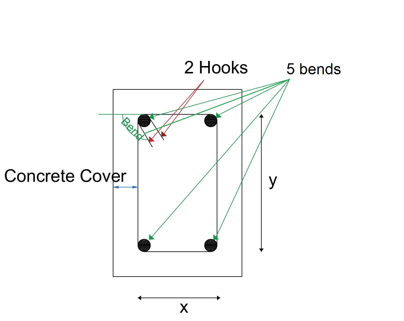
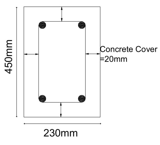
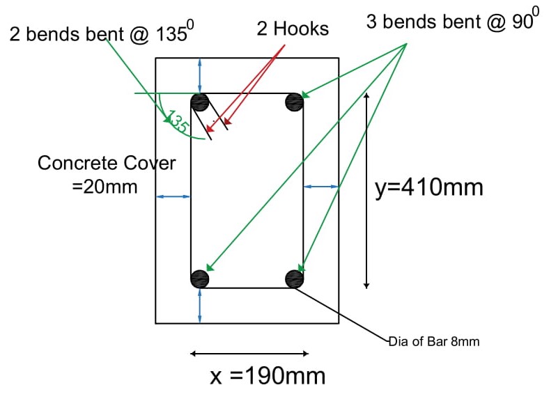
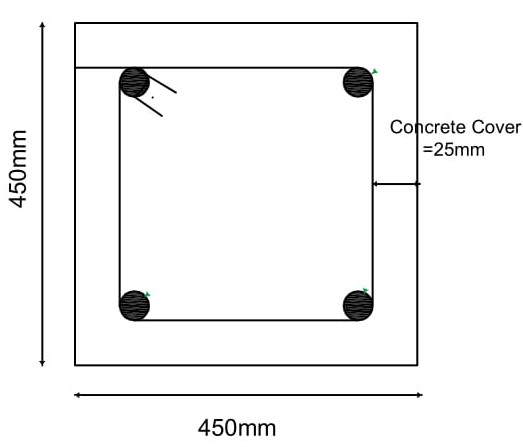
Reinforcement Detailing:

With Revit and its various add-ons and plugins, you can create 3D reinforcement designs in an advanced BIM environment. Furthermore, you can produce reinforcement shop drawings with rebar schedules.

Construction Documents:

Through Revit, you can create more thorough and accurate steel and concrete designs. Furthermore, thanks to the comprehensive building database, all of the elements from Revit models will correspond to real-world objects and materials. Therefore, other stakeholders and customers will be able to perceive your plans more vividly.

Structural Analysis:

Revit also allows you to conduct a cloud-based structural analysis while you continue to work on your construction project. Furthermore, you can run a few parallel analyses and analyze your Revit model partially or fully. Finally, Revit allows you to choose the format of the analysis results and what to do with them.

Linking With Steel Fabrication:

The interoperability between Revit and Advance Steel will provide you with a smooth BIM workflow from steel design to fabrication. Furthermore, Revit allows you to model connections in more detail using either parametric or custom steel connections. These features will not only increase the productivity of structural engineers but also significantly reduce mistakes in construction projects.

REVIT FOR DESIGNERS AND CONTRACTORS:

BIM 3D modeling has also helped MEP designers and contractors become both more effective and more efficient. Revit MEP helps employees dealing with mechanical, electrical, and plumbing planning and construction coordinate with other team members and fulfill their tasks as accurately as possible. Below, you’ll find what to expect from Revit if you are a part of the MEP industry.

Integrated Design:

Unlike CAD software, Revit allows you to streamline the engineering design process. Therefore, you can coordinate and communicate with architects and engineers before construction begins. Thanks to this level of automation, you are sure to come up with a solution that all stakeholders will accept.

Analysis:

Just like architects and structural engineers, MEP engineers also have various analysis tools at their disposal in Revit. These tools allow them to conduct simulations and run interference detection early in the process. Furthermore, you can use conceptual energy analysis data to examine annual energy costs and much more.

Documentation:

Revit also allows you to create, model, and document mechanical, electrical, and plumbing systems. Furthermore, these systems will be presented in the context of a full BIM project that includes architectural and structural components. Therefore, your documentation will be thorough and accurate.

Fabrication:

Finally, Revit helps MEP engineers create fabrication-ready models. Therefore, MEP contractors will immediately be aware of the materials and equipment needed for the production process. This fact, in turn, improves the workflow by reducing the communication chain.

REVIT PRICING:

After finding out how useful and important Revit is, you might be wondering about its price. First of all, we should note that perpetual licenses for Revit are not available. That being said, you can choose one of the subscription plans available on Autodesk’s webpage. The pricing of a single-user Revit license is shown in the chart below.

Subscription Plan Price
Annual subscription $2,545
Three-year subscription $6,870

Furthermore, if your line of work requires you to use other Autodesk software alongside Revit, you might want to consider Autodesk’s AEC industry collection. Architecture, Engineering & Construction Collection features various CAD and BIM software such as Revit, AutoCAD, and Civil 3D. These programs complement each other perfectly, especially since all of them can work with .dwg files.

Plus, the price of the bundle is much lower than if you were to buy all of these programs separately. In fact, you can save as much as $8,000 every year if you purchase it as a Collection.

Finally, you can buy Revit through an authorized reseller who will cater to your specific needs while also providing you with the same price. Plus, you get technical support. Microsol Resources deliver integrated solutions and services from implementation services to training that is needed to ensure our customer’s success.

IN CONCLUSION:

Although BIM isn’t a new concept by any means, it’s obvious that it is the future of the AEC industry. Hopefully, this article helped you become aware of the enormous potential of BIM software Revit and the way it can be utilized in architecture, engineering, and construction.

Source: microsolresources.com 

Sunday, June 11, 2023

The Power of Reversible Hydrogen Fuel Cells: Separating Hydrogen and Oxygen from Water


Introduction:

The quest for clean and sustainable energy sources has led to significant advancements in the field of hydrogen fuel cells. One of the key challenges in harnessing hydrogen as an energy carrier is the separation of hydrogen and oxygen gases from water. In recent years, reversible hydrogen fuel cells have emerged as a promising solution for this task. In this article, we will explore the workings of reversible hydrogen fuel cells and their role in efficiently extracting hydrogen and oxygen from water.


Understanding Reversible Hydrogen Fuel Cells:


Reversible hydrogen fuel cells, also known as reversible proton exchange membrane fuel cells (PEMFCs), are a variant of traditional PEMFCs. While conventional PEMFCs generate electricity from hydrogen gas, reversible fuel cells can operate in reverse mode, enabling the production of hydrogen and oxygen gases from water.


Mechanism of Action:


Reversible hydrogen fuel cells operate through a series of electrochemical reactions that take place within the cell. Let's dive into the detailed process:


1. Electrolysis Mode:


In the electrolysis mode, an external electrical current is supplied to the reversible fuel cell, initiating the splitting of water molecules into hydrogen and oxygen gases.

  • At the anode:

2H2O (liquid) → 4H+ (protons) + 4e- (electrons) + O2 (oxygen gas)

  • At the cathode:

4H+ (protons) + 4e- (electrons) → 2H2 (hydrogen gas)


When the electrical current is applied, water molecules at the anode are oxidized, releasing protons (H+) and electrons (e-). The protons migrate through a proton exchange membrane to the cathode, while the electrons flow through an external circuit. At the cathode, the protons and electrons combine, resulting in the production of hydrogen gas.


2. Fuel Cell Mode:


During the fuel cell mode, hydrogen gas and oxygen gas are supplied to the reversible fuel cell, which then generates electrical energy through the reverse reaction.

  • At the anode:

2H2 (hydrogen gas) → 4H+ (protons) + 4e- (electrons)

  • At the cathode:

O2 (oxygen gas) + 4H+ (protons) + 4e- (electrons) → 2H2O (liquid)


In this mode, hydrogen gas is oxidized at the anode, releasing protons and electrons. The protons migrate through the proton exchange membrane to the cathode, while the electrons flow through an external circuit, generating electrical power. At the cathode, oxygen gas combines with protons and electrons to form water.


Note: This animation from FREUDENBERG Youtube Channel will remove your confusion about Electrons migration and producing Electricity.


Efficiency and Advantages:


Reversible hydrogen fuel cells offer several advantages over traditional electrolysis methods for hydrogen production. Firstly, they are highly efficient, allowing for the conversion of electrical energy into chemical energy (hydrogen) with minimal energy loss. Secondly, these fuel cells can be integrated with renewable energy sources, such as solar or wind power, enabling sustainable hydrogen production. Furthermore, reversible fuel cells provide the flexibility to switch between electrolysis and fuel cell modes, making them versatile for various applications.


Conclusion:


Reversible hydrogen fuel cells represent a significant leap forward in the field of hydrogen separation from water. By leveraging the principles of electrochemistry, these innovative cells enable the efficient extraction of hydrogen and oxygen gases. With their high efficiency and adaptability, reversible fuel cells hold great potential for a sustainable and clean energy future, providing an eco-friendly alternative to traditional fossil fuel-based systems.


Once again, many thanks from ELBCAMPUS administration for providing us such an interesting subject with great practical methods.


Naeem Nekmal

Hamburg, Deutschland

June, 2023

Friday, June 9, 2023

Our Visit from IBA HAMBURG, Introduction and Purpose of this Innovative Building

IBA DOCK: A Hub of Innovation and Inspiration in Hamburg

Introduction:

The IBA DOCK not only houses the exhibition of the International Building Exhibition 2006-2013, but is also itself an exhibit of  innovative building and energy-saving technologies: the building is situated on an approximately 50-metre-long and 26-metre-wide concrete pontoon; the superstructures are made of steel in modular construction. This saves weight and makes it possible to remove a part of the superstructures in case of transport, so that the IBA DOCK can also navigate under low bridges. The IBA DOCK was designed by the Han Slawik Architectural Bureau in Hannover; the 10-month construction period was coordinated by the municipal development company ReGe Hamburg Projektrealisierungsgesellschaft (Project Realisation Company) mbH.

What is the purpose of the IBA HAMBURG?

  1. A Center of Inspiration: IBA DOCK is a place where architects, urban planners, researchers, and enthusiasts come together to share knowledge and inspiration. The dynamic atmosphere encourages dialogue, fostering the exchange of ideas that push the boundaries of architectural and urban design. Whether through exhibitions, workshops, or conferences, IBA DOCK sparks creativity and fuels innovation.
  1. Architectural Exhibitions: The exhibition spaces at IBA DOCK showcase an impressive collection of architectural projects, highlighting the latest trends and advancements in the field. From scale models to digital presentations, these displays immerse visitors in a world of visionary designs. Here, today on 08, June 2023 we witness the evolution of urban landscapes, explore sustainable building techniques, and discover groundbreaking concepts that redefine our perception of cities.
  1. Collaborative Workshops: IBA DOCK is not just a passive showcase; it actively engages visitors through interactive workshops and design charrettes. These collaborative sessions bring together architects, designers, and urban planners to tackle real-world challenges, brainstorm ideas, and propose innovative solutions. The workshops at IBA DOCK foster interdisciplinary collaboration, nurturing a spirit of cooperation and creativity.
  1. Future-oriented Conferences: At IBA DOCK, thought-provoking conferences and symposiums take place, exploring the future of urban development and architectural trends. Experts from around the world gather to share their insights, research, and experiences, shaping the discourse on sustainable cities. These conferences inspire attendees to think critically and envision a more inclusive, environmentally friendly, and socially vibrant urban future.
  1. Networking and Idea Exchange: IBA DOCK is a melting pot of ideas, where professionals and enthusiasts can network, forge connections, and find potential collaborators. From casual conversations over a cup of coffee to structured networking events, IBA DOCK cultivates an environment that fosters meaningful connections. These interactions often lead to innovative partnerships, further fueling the advancement of architectural and urban design.


Conclusion: IBA DOCK embodies the spirit of exploration, innovation, and collaboration that drives the architectural and urban design community in Hamburg. With its dynamic exhibitions, interactive workshops, inspiring conferences, and vibrant networking opportunities, IBA DOCK serves as a catalyst for change and progress. By bringing together visionaries and enthusiasts, it fosters a shared vision of sustainable, livable, and aesthetically pleasing urban spaces. Whether you're an architect, a student, or simply someone passionate about the future of cities, a visit to IBA DOCK promises to ignite your imagination and leave you inspired.

at last but not least, On behalf of all my classmates I am really thankful of ELBCAMPUS Management and Organizers especially Mr. Heornicke, Mr. Dolgij and Mrs Gesa von Maydell for such an Interesting class and site visits.

Naeem Nekmal

09, June 2023

Hamburg, Germany

Saturday, December 12, 2020

Density of Aggregate - Bulk and Relative Density


Density is an important parameter for aggregate. For aggregates, density is determined by multiplying the relative density (specific gravity) of the aggregate times the density of water.

Bulk Density of Aggregate [1]

The bulk density or unit weight of an aggregate is the mass or weight of the aggregate that required to fill a container of a specified unit volume.

Bulk Density = Mass/volume

Key Features:

  • If the volume is unit then, Bulk Density= Mass.
  • Unit in kg/m3 or lb./ft3.
  • In this definition, the volume is that contains both the aggregates and the voids between aggregates particles. 
  • The approximate bulk density of aggregate that is commonly used in normal-weight concrete is between 1200-1750 kg/m3 (75-110 lb./ft3)
  • Here, the Standard test method for determining the bulk density of aggregates is given in ASTM C 29 (AASHTO T 19). [2]

Relative Density of Aggregate [1]

The relative density (specific gravity) of an aggregate is the ratio of its mass to the mass of an equal volume of water.

Relative Density = Mass of the Aggregate/Mass of equal volume of water

Key Features:

  • Most aggregates have a relative density between 2.4-2.9 with a corresponding particle (mass) density of 2400-2900 kg/m3 (150-181 lb./ft3).
  • Here, for coarse aggregates, the standard test method has been explained in ASTM C 127(AASHTO) and for fine aggregates, the standard test method has been explained in ASTM C 128 (AASHTO). [3] 
  • The relative density of an aggregate can be determined on an oven-dry basis or a saturated surface-dry (SSD) basis.

Saturday, October 31, 2020

Quantity of Cement, Sand & Water required for Plastering:


Plastering refers to protecting a wall or ceiling by laying a plaster (Cement plaster). Plastering is done to remove surface imperfections caused by brickwork and to keep the surface smooth for painting.


There are many different types of plastering materials out of them, cement plaster is extensively used. Some other types of plastering materials include lime plaster, clay plaster, etc.


How to select the right plastering material for your house?

In any type of plastering two major factors are considered they are Surface Protection and the cost of material. If the quality of plastering is increased and taken higher, then the cost is affected. If price is considered and Quality of plaster are taken lesser importance then the surface protection is compromised.


Plastering material should be cheap and economical.

It should be durable enough to sustain any climatic changes in the entire life span of structure.

Plastering material should have excellent workability which can be applied during any weather conditions.

Let us calculate the quantity raw materials (Cement, Sand & water) required for cement plaster. Though the same process is applicable for any other types of plastering materials.


Contents [show]


Calculating the quantities of Cement & Sand required for plastering:

General points to be remembered in Plastering work calculation


The ratios mentioned in plastering are volumetric ratios of Cement & Sand (Ex. Cement: Sand = 1:5, 1 part of cement and 5 parts of sand in a mortar).

The overall thickness of plastering should be minimum 20mm including two coats.

Cement has a dry density volume of 1440Kg/m3

Each bag of cement weighs = 50 Kgs or 110 lbs.

The Volume of each cement bag = 50Kgs/1440 = 0.0348 m3.

The dry density of sand = 1600Kgs/m3

The plastering is done in two layers (two coats): The first coat of plastering is laid with the thickness of minimum 12mm (usually ranges between 12-15mm) and this coat is called as a Rough coat or Primary coat.

The second coat should be laid with the thickness of 8mm and this is called as a Finish coat or Secondary coat of plastering.

Total Plastering = First coat + Second Coat


Different ratios of Cement mortar used for plastering are tabulated below:

Mix Ratio             Areas of usage

1:6 & 1:5              This ratio is usually used for Internal plastering of bricks

1:4          Used for Ceiling and external walls

1:3          As it’s a rich mortar mix and it is used where external walls are prone to severe climatic conditions.

It is also used for repair works.


Steps involved in calculation of plastering quantities:

Find the total area of wall to be plastered in Sqm (m2).

Consider the ratio and thickness of plastering

Calculate the Total Volume of Plastering

Find out the Volume of Cement and Sand individually for both the coats

Calculate the total volume of cement & Sand required for plastering

Now coming to the calculation part,


We are considering the below values for calculation purpose:


Wall width and height is 10m and 10m.

Ratio of First coat of plastering (Cement: Sand = 1:5) with the thickness of 12mm.

the ratio of secondary coat of plastering (Cement: Sand = 1:3) with the thickness of 8mm.

Step 1: Calculate the Area of Plastering

Area = width x height = 10 x 10 = 100m2


Step 2: Find the Volume of Plastering


Volume of First Coat = Area of Plastering x Thickness of Plastering


= 100m2 x 12mm (Convert mm to m)


= 100×0.012 = 1.2m3


Hence, Volume of First Coat of Plastering = 1.2m3


The volume of Second Coat = Area of Plastering x Thickness of Plastering


= 100m2 x 8mm (Convert mm to m)


= 100×0.008 = 0.8m3


Therefore, Volume of Second coat of plastering = 0.8m3

 a

Step 3: Finding the individual quantities of Cement and Sand.

First coat ratio = 1:5 (1 part of Cement and 5 parts of Sand)


Total parts = 1+5 = 6


Quantity of Cement required for First coat =


(Total Volume of first coat plastering x No. of Parts of cement) ÷ Total Parts


= 1.2 x 1/6 = 0.2m3


Quantity of Sand required for First coat =


(Total Volume of first coat plastering x No. of parts of sand) ÷ Total Parts


= 0.8 x 5/ 6 = 1.0m3


Similarly, for Second coat,


Second coat ratio = 1:3 (1 part of cement and 3 parts of sand)


Total parts = 1+3 =4


Quantity of Cement required for Second coat


= (Total Volume of second coat plastering x No. of Parts of cement) ÷ Total Parts


= 0.8 x 1/4 = 0.2m3


Quantity of Sand required for Second coat


= (Total Volume of second coat plastering x No. of parts of sand) ÷ Total Parts


= 0.8 x 3/4 = 0.6m3


Step 4: Finding the quantity of water required for plastering:

Amount of water to be added in mix depends upon the moisture content present in cement, sand & atmosphere.


Quantity of water = 20% of total dry material (Cement + Sand)

= 20% of (574+2560) = 0.2 x 3134 = 627 liters.


Final Result:

As mentioned above volume of 1 bag of cement (50kgs) = 0.0348m3

For 0.4m3 = 0.4 x 50 / 0.0348 = 574Kgs = 11.4bags


Similarly, for Sand 1m3 = 1600Kgs.

1.6 m3 = 1.6 x 1600 = 2560Kgs = 2.5tonnes

Quantity of Water required = 627litres.


How many bags of cement are required for 1 square meter of plastering?

If the above-mentioned values are considered for this then (Rough estimate)


From above, 100m2= 574 Kgs of cement

1m2 = 574/100 = 5.7Kgs


Summary:


Quantity of Cement, Sand & Water required for Plastering. For 100m2 of Wall, if first & second coat of cement mortar ratio 1:5 & 1:3 laid then

The Quantity of cement required = 574Kgs

Calculated Quantity of Sand (Fine aggregate) required = 2560Kgs

Quantity of Water required = 627 litters.

Thursday, May 21, 2020

Chlorine Removal from Your Drinking Water


Watch this video to know how much chlorine your tap water may have. What happens to chlorine in water when you wash fruits and vegetables in such water? How much chlorine you daily intake and why Kangen Water Machine is required to remove this chlorine from your water.

Common Drinks and their pH Level


Watch the video to understand how Acidic or Alkaline is water and beverages you drink every day. How Healthy or Unhealthy it is for you.

What is ORP (Oxidation Reduction Potential)


Antioxidants in Kangen Water Antioxidants are measured in terms of Oxidation Reduction Potential (ORP). While +ve ORP implies Oxidising, Aging and bad for you, the -ve ORP indicates powerful Antioxidants. Watch the Video and know the ORP Levels of your Favorite Drinks.

Monday, May 11, 2020

How to calculate Cutting length of Stirrups in Beam and column


How to calculate Cutting length of Stirrups in Beam and column

To cater to the stresses and loads in RCC, Bars are bent to different shapes in the bar bending schedule.
Different shapes of bars have different cutting lengths. In this post, we are going to explain to you “How to calculate or find the cutting length of Stirrups for different shapes”.
Remember,
The transverse reinforcement provided in Column is called Ties and the transverse reinforcement provided in Beam is called Stirrups. But on-site, we usually call both transverse reinforcements as Stirrups.
The prime reason for providing the stirrups in the beam is for shear requirements and to keep the longitudinal bars in position.
Deducting the concrete cover is most important in Bar bending, if you don't know how to deduct the concrete cover then refer this post

Steps involved in finding the cutting length of stirrups:-

  1. Look at the size of column or beam from drawings
  2. Adopt Dia of the bar (generally 8mm Dia is used for stirrups)
  3. Deduct the concrete cover or clear cover
  4. Find the total outer length of stirrup after deducting concrete cover.
  5. Add the length of the hook to the length of the stirrup
  6. Deduct the length of bends
  7. Use below formula to find the total cutting length of stirrups

Formula: Cutting Length of Stirrups = Perimeter of Shape + Total hook length – Total Bend Length

Important Basic formulas:
Perimeter of Rectangle = 2 ( length + breadth)
Perimeter of Square = 4 x side length
Perimeter of circle or Circumference of Circle = 2πr = πd (r= radius, d= Diameter of Circle)

Typical Diagram of Stirrup:-

Refer the below image of the typical diagram of stirrup for clear understanding about x & y length, bends, hooks, and concrete cover.
typical stirrup diagram
In the above image, there are 5 bends at 4 corners, 2 hooks, and concrete cover around the stirrup.
x = length of the stirrup in the x-direction after deducting concrete cover &
y = length of the stirrup in the y-direction after deducting concrete cover.

Important standards used in Bends & Hooks:

The below standards are most important in calculating the hook length and bend lengths at corners while finding the cutting length of stirrups.
  • 1 Hook length = 9d or 75mm
  • 45° Bend length = 1d
  • 90° Bend length = 2d
  • 135° Bend length = 3d
Remember, d = Diameter of Bar

Cutting length for Rectangular Stirrups:-

The rectangular column or rectangular beam is the most commonly used shape of the column in any construction. In this shape of beam or column, a rectangular stirrup is usually adopted.
  1. Considering the below Rectangular column size 230mm x 450mm for calculation purpose
    rectangular column details
  2. Adopting Dia of Bar used for stirrups is 8mm
  3. Deducting the concrete cover 20mm from all sides
    x = 230 – 20-20 = 190mm
    y = 450-20-20 = 410mm
    cutting length of rectangular stirrup
  4. Total Length of the hooks:
    From fig, There are two hooks which mean 9d+9d = 18d
  5. Total Length of Bends:
    From above fig, There are 3 bends which are bent at an angle of 900 and two bends are bent at an angle of 1350
    Total bend length = 3 x 900 Bend length + 2 x 1350 Bend length = 3 x 2d + 2 x 3d = 12d = 12 x 8 = 96mm
Total Cutting length of Rectangular Stirrup = Perimeter of Rectangle + Total Hook length – Total Bend Length
= 2 (x+y) +18d – 12d = 2(190 + 410) + 18 x 8 – 12 x 8 = 1248mm = 1.248m

Cutting length for Square Stirrups:-

  1. Considered the column size as 450mm x 450mm
    square stirrup details
  2. Adopting Dia of Bar used for stirrups is 8mm
  3. Deducting the concrete cover 25mm from all sides (in the square all sides are equal)
    x = 450- 20-20 = 410mm
    y = 450-20-20 = 410mm, Hence x = y (in square all sides are equal)
    Square stirrup deductions
  4. Total Length of the hook:
    There are two hooks which mean 9d+9d = 18d
  5. The total length of Bends:
    There are 3 bends that are bent at an angle of 900 and one is bent at an angle of 1350.
    Total bend length = 3 x 900 Bend length + 2 x 1350 Bend length = 3 x 2d + 2 x 3d = 12d = 12 x 8 = 96mm
    square stirrup details
Total Cutting length of Square Stirrup = Perimeter of Square + Total Hook length – Total Bend Length
= 4 x 410 +18d – 12d = 1648mm = 1.64m

Cutting Length for Circular Stirrup:

  1. Considered the column dia as D = 1000mm
  2. Adopting Dia of Bar used for stirrups is d =8mm
    Circular Stirrups details
  3. Deducting the concrete cover from diameter of column
    D = 1000-25-25 = 950mm
    circular stirrup with hooks and bends
  4. Circumference length of Ring = πD = 950 x 3.14 = 2983mm
  5. Total Length of the hook:
    There are two hooks which means 9d+9d= 18d
  6. Total Length of Bends:
    There are 2 bends which are bent at an angle of 1350
    Total bend length = 2 x 1350 Bend length = 2 x 3d = 6d= 6 x 8 = 48mm
Total Cutting length of Circular Stirrup or Ring = Circumference of Circle + Total Hook length – Total Bend Length= 2983 +18d – 6d =3079mm =3.07m

Cutting Length for Triangular Stirrups:

  1. Considered the Column size 400mm x 450mm
    traingular stirrup details
  2. Adopting Dia of Bar used for stirrups is d = 8mm
  3. Deducting the concrete cover 25mm from all sides
    x = 400-20-20 = 360mm
    y = 450-20-20 = 410mm
    From Pythagorean theorem,
    Hypotenuse2=(Opposite)2 + (Adjacent)2 
    finding hypotnuse in triangular stirrup
    look at 2nd triangle in above image
    H2=(x/2)2 + y2
    H2=1802 + 4102 => =  √(447)2  = 447mm
    The total length of stirrup till now = 2 x H + 360 = 2 x 447 + 360 = 1254mm
  4. Total Length of the hooks: 
    There are two hooks which means 9d+9d= 18d
    Triangular stirrup Hooks and Bend Lengths
  5. Total length of Bends:
    There are 4 bends which are bent at an angle of 1350
    Total bend length =4 x 1350 Bend length=  4 x 3d = 12d= 12 x 8 = 96mm
Total Cutting length of Triangular Stirrup = Perimeter of Triangle + Total Hook length – Total Bend Length
= 1254+18d – 12d = 1302mm = 1.3m

Cutting Length for Diamond Stirrups:

  1. Considered the Column size 400mm x 400mm
    diamond stirrup details
  2. Adopting Dia of Bar used for stirrups is d = 8mm
  3. Deducting the concrete cover 25mm from all sides
    x = 400-20-20 = 360mm
    y = 400-20-20 =360mm
    diamond stirrups hook length and bend length
    From Pythagorean theorem,
    Hypotenuse2=(Opposite)2 + (Adjacent)2 
    H2=(x/2)2 +( y/2)2
    H2=1802 + 1802 => =  √(254)2  = 254mm
  4. The total length of stirrup = 4 x H  =4 x 254 = 1016mm
  5. Total Length of the hook:
    There are two hooks which means 9d+9d= 18d
  6. Total length of Bends:
    There are 3 bends which are bent at an angle of 90 + 2 bends which are bent at an angle of 1350
    Total bend length = 3 x 900 Bend length + 2 x 1350 Bend length= 3 x 2d + 2 x 3d = 12d = 12 x 8 = 96mm
Total Cutting length of Diamond  Stirrup = Perimeter of Diamond shape + Total Hook length – Total Bend Length= 1016+144-96 = 1064mm = 1.064mm
I hope now you can easily find the cutting length for different types of stirrups.